


35
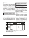
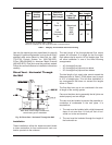
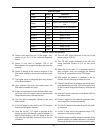
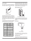
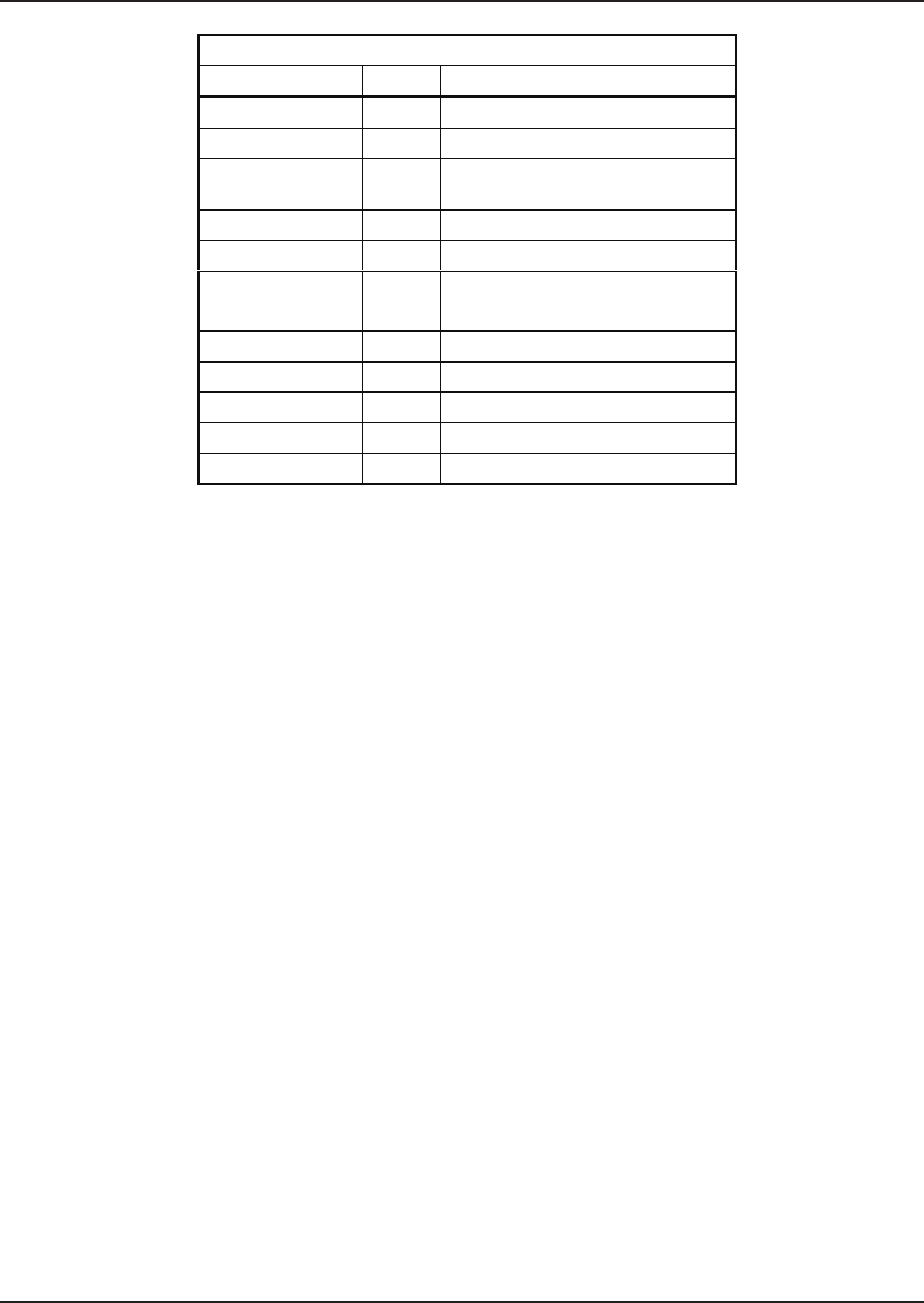
External Lights
Light Color Indication
Power Blue Main power is on
Call For Heat Yellow Thermostat is closed
Safety Red
One or more safeties is inopera-
tive
Ignition Red Ignition module is inoperative
Flow Green Flow is present
Blower 1 Green Blower 1 is on
Blower 2 Green Blower 2 is on
Blower 3 Green Blower 3 is on
Stage 1 Green Stage 1 is on
Stage 2 Green Stage 2 is on
Stage 3 Green Stage 3 is on
Stage 4 Green Stage 4 is on
Table M: Status LED Indicators
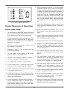
24. Power is also sent from pin 2 of the stage 1 con-
nection to pin P1-3 of the universal diagnostic
board.
25. Power is now sent to terminal TP4 of the
Economaster II to energize the relay and close the
contacts.
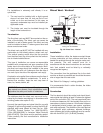
26. Power is waiting at the common terminal of the
flow switch waiting for closure and sufficient water
flow.
27. The heater pump is energized upon relay closure
of the Economaster II.
28. Upon sufficient flow from the heater pump, the
flow switch contacts will close.
29. If there is insufficient flow and the flow switch does
not close, a 24 VAC signal is sent to the Universal
Diagnostics Board to indicate the fault.
30. The flow light is energized; located on the front
status panel.
31. A 24 VAC signal is also sent to the “TH” terminal
located on the ignition module.
32. Once the 24 VAC “TH” signal is received at the
ignition module, the internal contacts between F1
and F2 close sending a 120 VAC signal to the 120
VAC pilot duty terminals, located at J14 on the cir-
cuit board.
33. The 120 VAC signal continues to the coil of the
blower relay K-3 (N.O.).
34. The 120 VAC signal continues to the 120 VAC
safety terminals located at J13 on the circuit
board.
35. When the coil on relay K-3 is powered, the N.O.
relay contacts close and energize the blowers
from the J8 connections on the CPW board.
36. After proper air pressure is received in the air
plenum, the air pressure switches will close.
37. If there is insufficient air pressure and the air pres-
sure switches do not close, a 24 VAC signal is sent
to the Universal Diagnostics Board to indicate the
fault.
38. A 24 VAC signal is now sent to the blower LED on
the status board.
39. Power is applied to the optional equipment inter-
lock connection (normally jumpered).
40. The 24 VAC signal is then sent to the 24 VAC safe-
ty connector.
41. 24 VAC is now sent to the pressure switch (P.S.)
terminal on the ignition module.
42. Once the pressure switch signal is received at the
ignition module, the heater performs a 15-second
pre-purge, and then the hot surface igniter is ener-