


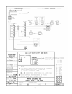
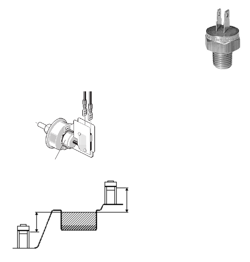
PRESSURE SWITCH
The pressure switch, or heater actuator, ensures that
the heater operates only when the filter pump is in
operation. It is factory set at 1.75 PSI for deck level
installations. When the heater is located below the level
of the spa or pool it may be necessary to reset the
pressure switch to compensate for the no-flow static
head. If it is necessary to reset the pressure switch, we
recommend the following procedure:
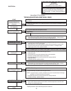
PRESSURE SWITCH ADJUSTMENT:
1. Make sure the pool filter is clean before adjusting
the switch.
2. Set the heater control to the OFF mode.
3. Turn the filter pump on and confirm that the pressure
switch is closed (use a multimeter to check). If the
pressure switch fails to close, either the switch setting is
too high or the filter pump is not supplying enough
pressure.
4. Turn the heater ON.
5. Manually turn the pressure adjustment knob clock-
wise until the heater shuts off. (A flat screw driver may be
necessary if knob is too tight).
6. Slowly turn the adjustment knob counter-clockwise
until the heater calls for heat again.
7. Turn an additional 1/2 turn counter-clockwise.
8. While the heater is running, check the adjustment by
turning the pump off and on several times. The burners
should shut off immediately when the pump is turned off.
If it does not, repeat the above steps until proper operation
is observed.
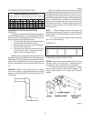
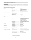
ADJUSTMENT KNOB Fig. # 8069.1
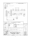
PRESSURE SWITCH ADJUSTMENT RANGE
NOTE: If heater is installed outside of the limits shown,
a flow switch must be used in place of the pressure switch
when mounted and wired adjacent to the heater.
20
TWO SPEED PUMPS
In some cases, the flow on the low speed is insuffi-
cient to operate the heater. This is apparent when the
pressure switch cannot be further adjusted or if the heater
makes banging noises. In these cases, the pump must
be run at high speed when heating the water.
CAUTION: Do not operate the heater without a function-
ing and properly adjusted pressure switch.
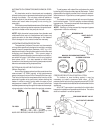
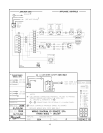
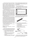
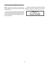
HIGH LIMITS
The heater is equipped with two automatic high limits.
Set to operate at 135°F and 140°F.
NOTE: An erratic high limit is often characteristic of
internal heat exchanger problem, i.e. scale build-up,
U.G. operation. Refer to troubleshooting sections.
Fig. # 9275
HIGH LIMIT REMOVAL
1. Shut off main electrical power switch to heater.
2. Remove inspection panels.
3. Drain heater.
4. Remove defective high limit and replace with a
new high limit.
5. Reverse above procedure to re-install.
PILOT SAFETY
The heater employs a pilot safety which closes the
main gas valve within 8/10ths of a second whenever the
pilot flame is interrupted. Pilot flame is automatically lit
when the device is powered. Unit performs its own safety
check and opens the main valve only after the pilot is
proven to be lit.
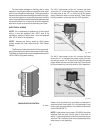
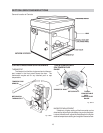
BURNER DRAWER REMOVAL
1. Shut off main electrical power switch to heater.
2. Shut off gas upstream of heater.
3. Remove front door.
4. Disconnect gas line from gas valve.
5. Remove (2) screws that mount burner tray to
unit, and (2) screws that secure gas valve to
jacket.
6. Disconnect wires that terminate at gas valve.
7. Slide out burner tray.
8. Reverse above procedure to reinstall.
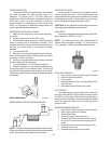
5' Max
5' Max