


118 Chapter 8 Analyzing Digital Sources and Cables
Testing cables and distribution systems
This section describes how to test HDMI or DVI cables, and distribution systems using
pseudo-random noise. Using different signal formats, the HDMI/DVI cable can be tested
over a wide range of frequencies.
The procedures below provide instructions for testing cable and distribution systems with
the analyzer through the front panel. Note that you can also perform these procedures
through the command line. For procedures using the command line refer to “Analyzing
pseudo-random noise in a cable or distribution system” on page 133.
To test a cable or distribution system:
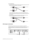
1. Connect the HDMI/DVI cable to be tested between the HDMI/DVI Tx and Rx connectors
on the generator.
Note: If you are testing a fiber optic cable, plug the fiber optic cable connector marked
“transmitter” to the HDMI/DVI Tx connector on the generator, and plug the connector
marked “receiver” to the HDMI/DVI Rx connector on the generator. Use a 5 Vdc power
supply adapter at the receiver side of the cable.
2. If necessary, set the proper HDMI/DVI signal source and pseudo-random noise
parameters within the generator.
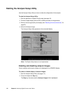
•See “Starting the Analyzer Setup Utility” on page 112 for steps on viewing the
current analyzer configuration.
• You will have to configure the analyzer for an internal source. To edit HDMI/DVI
signal source parameters, see “Setting up analyzer to measure timing” on page
114.
Note: The HDMI/DVI signal source must be set to internal (Auto Based On field set
to CURRENT) for this procedure.
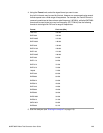
• For information on what values to set the pseudo-random noise parameters as well
as instructions on how to set them, see “Setting pseudo-random noise parameters”
on page 142.
3. (HDMI only) If desired, monitor the video signal received on the HDMI Rx connector
(see “Monitoring HDMI analyzer signal input” on page 110).