


10 — ENG
ASSEMBLY
Read this manual. Do not attempt to operate
equipment until you have read this Manual for
Safety, Operation, and Maintenance Instruc-
tions.
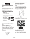
Grounding Lug
NOTE: This manual is a general manual. Informa-
tion in this manual may or may not pertain to your
model. Please read carefully.
NOTE: Left and right describes the location of a
part with the operator facing the outlet panel.
REMOVE GENERATOR FROM CARTON
• Open carton from top.
• Cut carton along dotted lines.
• Remove all carton inserts.
• Remove generator through opening in carton.
• (If equipped) See portability Kit instructions to
assemble the portability kit.
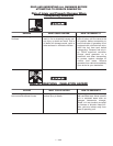
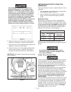
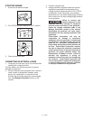
• (if equipped) Remove
shipping block from
under the gen head by
unscrewing the bolt and
remove the wood
block. It is very
important that this is
removed before starting your
generator. See Figure 1.
IMPORTANT: Before any attempt to start your genera-
tor be sure to check engine oil (See Engine Operator's
manual)
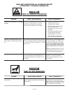
GROUNDING THE GENERATOR
A grounding lug is supplied with the generator for use
when required by local electrical ordinances. Refer to
article 250 of the National Electrical Code to clarify any
needed grounding information. Your local electric com-
pany or a certified electrician should be able to help
you with this information.
NOTE: Your engine is already grounded to the frame by
a grounding strap.
Figure 2
Figure 1
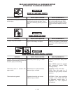
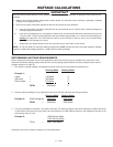
TYPICAL INSTALLATION OF BATTERY
● Recommended Battery for Electric
Start: 12V - 45 A H. or 210 CCA (Cold Cranking
Amps)
● Purchase battery and battery hardware separately,
not included with unit.
1. Place battery in rack with terminals facing towards
generator head.
2. Place battery bracket (A) over battery as shown in
Figure 3 (opposite battery terminals).
3. Place "L" bolt (B) through top and bottom brackets
and secure with wing nut (C).
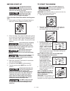
4. Locate the solenoid on the left side of the unit. See
Figure 4.
To Prevent sparks connect the red (positive)
cable to the positive (+) terminal before
connecting the black negative cable.
5. Remove the nut from the solenoid post and place
one end of the positive (red) battery cable onto the
post. Reassemble nut and tighten securely. See
Figure 4.
Nut
Positive (+)
Battery Cable
Solenoid
Figure 4
Figure 3