


8
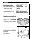
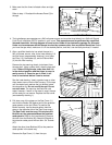
2. Make sure that the cap (not shown) is fully tightened
onto the end of the drain hose.
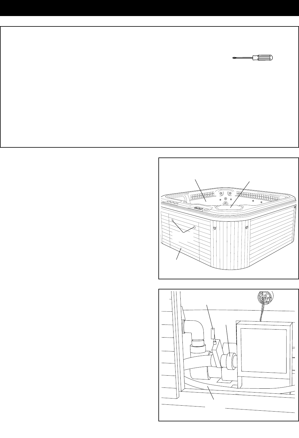
Locate the four gate valves inside the access open-
ing (there are two gate valves per pump). Open
each gate valve by pulling up on the handle until you
hear a click, indicating that the gate valve is locked
in the open position.
Make sure that the four collars are tightened (there
are two collars per pump).
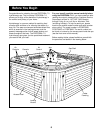
Before beginning assembly, carefully read the
following information and instructions:
• Place all parts in a cleared area and remove the
packing materials from the spa shell. Do not dis-
pose of the packing materials until assembly is
completed and the spa is operating.
• During assembly, make sure that all parts are
oriented as shown in the drawings.
• Read each assembly step before you begin.
• Tighten all parts as you assemble them, unless
instructed to do otherwise.
ASSEMBLY REQUIRES THE FOLLOWING
TOOLS (not included):
• One phillips screwdriver
• You will also need a small amount of soap and
a damp cloth.
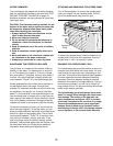
A wire connector is provided on the electronics
pack of the spa to connect a minimum No. 8
AWG (8.04 mm
2
) solid copper conductor
between the spa and any metal equipment,
electrical enclosure made of metal, metal water
pipes, or conduit within five feet of the spa.
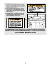
1. Before beginning assembly, make sure that you
have read and understand the information in the
box above and on the previous two pages.
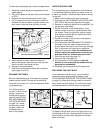
Remove the Access Panel (5) by inserting your fin-
gers into the indicated holes and pulling the Access
Panel away from the spa. Be careful not to damage
the spa shell.
Turn each of the spa jets clockwise as tightly as you
can. Then, turn each jet counterclockwise until it
stops.
Assembly
Drain
Hose
Collar
5
Holes
1
Spa Shell
Filter Cover
2
Gate Valve