


8
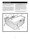
Before beginning assembly, carefully read the
following information and instructions:
• Place all parts in a cleared area and remove the
packing materials from the spa shell. Do not dis-
pose of the packing materials until assembly is
completed and the spa is operating.
• During assembly, make sure that all parts are
oriented as shown in the drawings.
• Read each assembly step before you begin.
• Tighten all parts as you assemble them, unless
instructed to do otherwise.
ASSEMBLY REQUIRES THE FOLLOWING
TOOLS (not included):
• One phillips screwdriver
A wire connector is provided on the electronics
pack of the spa to connect a minimum No. 6
AWG (13.3 mm
2
) solid copper conductor
between the spa and any metal equipment,
electrical enclosure made of metal, metal water
pipes, or conduit within five feet of the spa.
Assembly
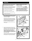
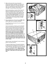
1. Before beginning assembly, make sure that you
have read and understand the information on
the previous two pages.
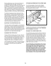
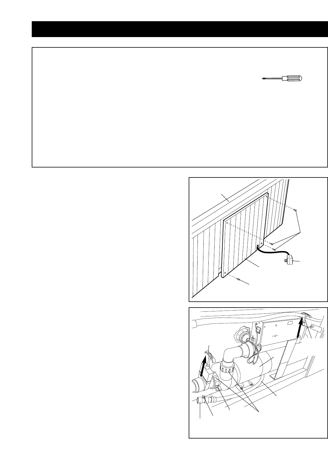
Remove the four cover screws from the access
cover. Remove the access cover from the Spa by
sliding the access cover down and pulling the bot-
tom of the access cover away from the Spa Unit.
Be careful not to damage the spa shell.
Remove the power cord with the GFCI (40) from
inside the spa.
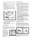
2. Locate and check the position of the two cut-off
valves. The cut-off valves must be open for proper
spa operation. To open a valve, hold the handle and
turn it until you can pull it out to the open position.
Open the other valve in the same manner.
Important: Occasionally the valves will be
closed at the factory during manufacturing. The
motor will be damaged if it is operated with the
cut-off valves closed.
Close the valve knob on the drain hose. Thread the
cap onto the drain hose. Thread the drain plug into
the Pump Motor (13). Tighten the pump fittings.
Access
Cover
Cover
Screws
Cover
Screw
Spa
Shell
40
1
Cut-off
Valve
Pump
Fittings
Cut-off
Valve
Drain
Plug
Drain Hose
Valve
Knob
Cap
13
2