


8
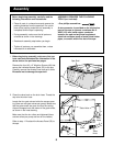
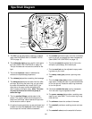
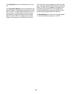
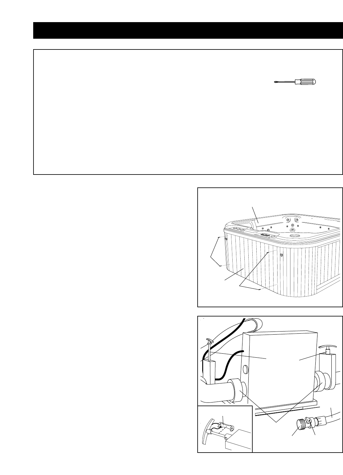
2. Close the valve knob on the drain hose. Thread the
cap onto the drain hose.
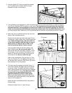
Locate the four gate valves inside the access open-
ing (there are two gate valves per pump). Make sure
that the gate valves are open and that the locking
clips are snapped onto the stems of the gate valves,
as shown in the inset drawing.
Make sure that the six collars are tightened (there
are two collars per pump and two on the heater).
Refer to step 1. Re-attach the Access Panel (25) to
the spa.
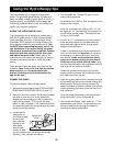
Before beginning assembly, carefully read the
following information and instructions:
• Place all parts in a cleared area and remove the
packing materials from the spa shell. Do not dis-
pose of the packing materials until assembly is
completed and the spa is operating.
• During assembly, make sure that all parts are
oriented as shown in the drawings.
• Read each assembly step before you begin.
• Tighten all parts as you assemble them, unless
instructed to do otherwise.
ASSEMBLY REQUIRES THE FOLLOWING
TOOLS (not included):
• One phillips screwdriver
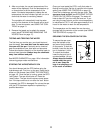
A wire connector is provided on the electronics
pack of the spa to connect a minimum No. 6
AWG (13.3 mm
2
) solid copper conductor
between the spa and any metal equipment,
electrical enclosure made of metal, metal water
pipes, or conduit within five feet of the spa.
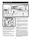
1. Before beginning assembly, make sure that you
have read and understand the information in the
above and on the previous two pages.
Remove the four #10 x 2” Machine Screws (46) that
secure the indicated Access Panel (25) to the spa.
Carefully remove the Access Panel and set it aside.
Be careful not to damage the spa shell.
Assembly
Collar
Cap
Valve
Knob
Drain
Hose
25
46
46
1
Spa Shell
2
Gate Valve
Locking Clip