


13
A
A
B
B
D
C
A
E
A
D
A
B
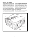
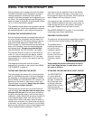
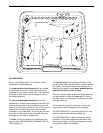
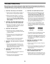
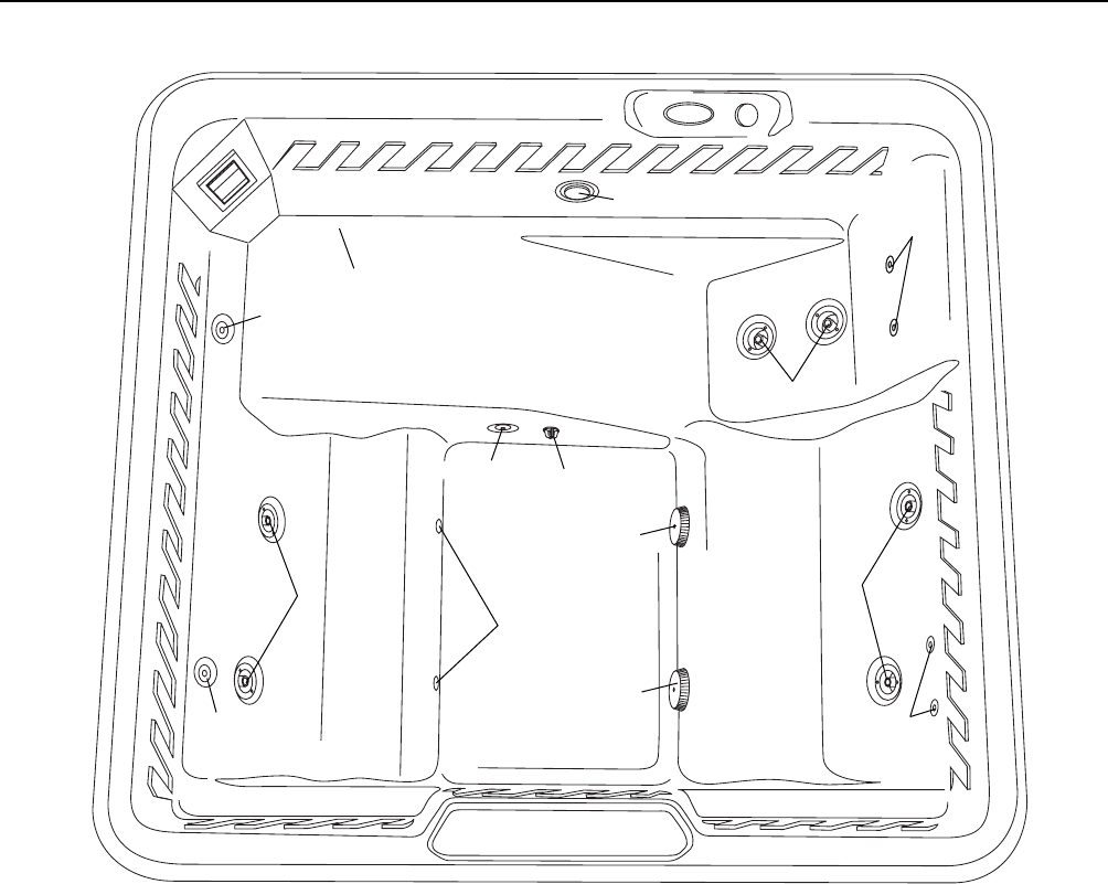
SPA SHELL DIAGRAM
SPA OPERATION
Refer to the diagram above. The function of each
component is explained below:
The eight uni-directional thera-jets (A) are located
on both sides of the spa. Five jets focus the water
massage on your upper or lower back. The remaining
three jets provide a foot hydro-massage for three of
the seating positions.
The six multi-directional thera-jets (B) can be
adjusted for a custom hydro-massage. Each thera-jet
can also be shut off by being pressed in and turned
back on by pulling the jet back out. Two of the jets are
located on the reclining seat and focus the water
massage on your lower back. Two more jets are locat-
ed on each of the bench seats, and focus the water
massage on your lower or middle back.
The filter (C) can be removed for replacement and
cleaning (see CHECKING AND CLEANING THE FIL-
TER on page 19).
The suction vents (D) located near the floor of the
spa brings the water into the pump in order to operate
the system. The suction covers should always be in
place over the suction vents. Never operate the spa
without the suction covers in place.
This spa is ozone ready. An optional ozone generator
can be installed to utilize the ozone jet (E). Ozone
provides a way to help sanitize your spa with minimal
chemical treatment.
The temperature probe (F) reads the current water
temperature, which is displayed on the console.
The RESTORATION 5.1 also has a light (G) for your
safety and convenience during evening use.
The RESTORATION 5.1 features automatic freeze
protection. If the water temperature falls below 40¡F,
the pump will begin circulating and heating the water
to prevent the water from freezing.
F
G