


Item 69728 69729
Page 7
For technical questions, please call 1-888-866-5797.
SAFETYOPERATIONMAINTENANCE SETUP
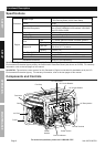
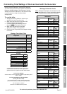
Components and Controls (cont.)
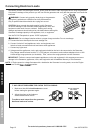
The following are descriptions of the controls
on the power panel. Your generator has
sockets to power your products with circuit
breakers to protect the voltage flow.
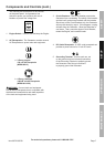
1.
I
O
Engine Switch: Used to start and stop the Engine.
2. AC Receptacles: The Generator contains several
AC Receptacles to power tools and equipment.
a. 3-Prong, duplex
120 volt AC Receptacle
(NEMA #5-15)
b. 4-Prong, twistlock
120/240 volt AC Receptacle
(NEMA #L14-30)
WARNING! Connect tools and equipment
only to the AC Receptacle that is compatible with
the electrical characteristics and rated capacities
of the tools and equipment being used.
3.
ON
OFF
Circuit Breakers: The circuit breaker protects the
Generator from overloading. The rating of the breaker
and the load it protects are marked near the breaker.
Should any of the Circuit Breakers trip, the Generator
will stop the electricity output. If this happens, unplug
all loads from the Generator. Allow the Generator to
cool down. Then, press the tripped Circuit Breaker,
restart the Engine, and re-attach loads.
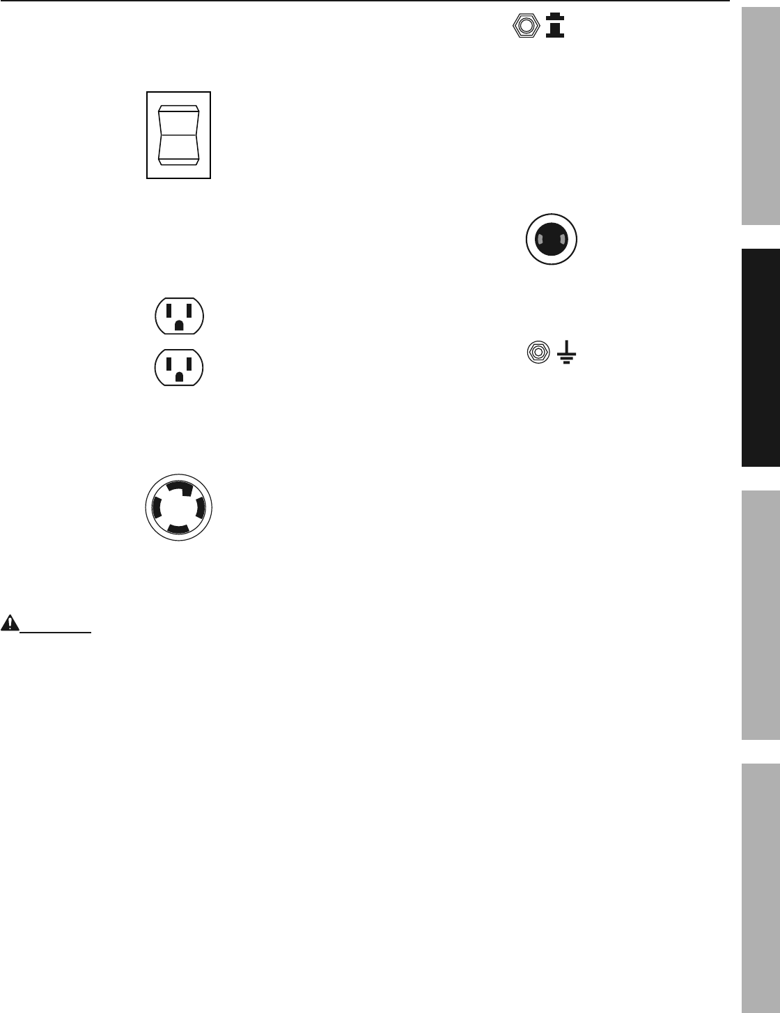
4. DC Outlet Receptacle: 12 VDC outlet receptacle set
provides a power source for 12 volt DC items.
5. Grounding Terminal: Prior to each use, set
up the ground wire (not included) connection
to the Grounding Terminal to properly ground
the Generator. See Set up instructions
to properly ground the Generator.