


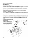


*13 HP Honda OHV engine
*Cast-iron cylinder sleeve
*Low oil sensor
*Receptacles on control panel
*Idle control
*CordKeeper™
*7 gallon metal fuel tank
*Spark arrester
*Portability Kit
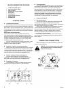
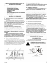
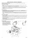
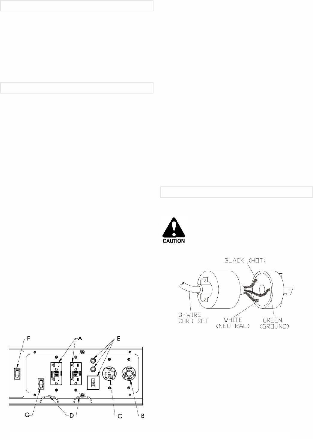
A.120 Volt GFCI Receptacle
Ground Fault Circuit Interrupter duplex receptacle is rated
so that a total of 20 amps may be drawn regardless of whether
both halves or just one receptacle is used. This receptacle may
be used along with other receptacles provided the generator is
not overloaded and total power drawn is kept within nameplate
ratings.
Ground Fault Circuit Interrupter
(Conforms to U.L 943, Class A and NEC requirements)
This device protects you against hazardous electrical shock
that may be caused if your body becomes a path through which
electricity travels to reach ground. This could happen when
you touch an appliance or cord that is “ live “ through faulty
mechanism, damp or worn insulation, etc.
The GFCI receptacle cannot be reset once tripped, unless
the generator is running and power is available to it. Test
regularly to assure proper operation.
B.120/240 V, 30 Ampere Twistlock Receptacle
Maximum full load current may be drawn from the 120/240
volt receptacle, provided it is the only receptacle used. Total
current must be limited to the nameplate rating. If the 120/240
volt receptacle is used along with the 120 volt receptacle, the
total load drawn must not exceed the nameplate ratings.
C.120 Volt, 30 Ampere Twistlock Receptacle
You may draw a maximum of 30 amps from this
receptacle. If other receptacles are used at the same time,
total power used must be kept within nameplate ratings.
D.CordKeeper™ Restraint
The CordKeeper™ restraint is a unique feature used to
prevent plugs from being pulled out of the receptacles.
E.Circuit Protectors
The receptacles are protected by an AC circuit protector. If
the generator is overloaded or an external short circuit occurs,
the circuit protector will trip. If this occurs, disconnect all
electrical loads and try to determine the cause of the problem
before attempting to use the generator again. If overloading
causes the circuit protector to trip, reduce the load. NOTE:
Continuous tripping of the circuit protector may cause
damage to generator or equipment. The circuit protector
may be reset by pushing the button of the protector.
F.Engine On/Off Switch
G.Idle Control Switch
The Idle Control circuit is designed to extend engine life
and improve fuel usage by slowing the engine down to
approximately 2200 RPM in a “No Load” condition. The noise is
also greatly reduced during this condition.
When power is required from the generator an electronic
control module automatically senses current flow in the
electrical outlet and allows the engine to return to full speed or
standard operating condition. Likewise, when the load is
removed, the generator will automatically return to the idle
condition after a 4-5 second delay.
A convenient switch is mounted in the control panel for
easy access and will disable the Idle Control circuitry when in
the off position.
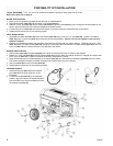
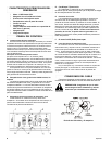
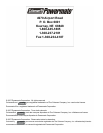
Refer to the diagram for proper connection of power cord
wires to the plug terminals.
CAUTION: Insure that the power cord used is
well insulated and has a sufficient rating to
match that of the plug.
2
English
CONTROL PANEL
MAJOR GENERATOR FEATURES
POWER CORD CONNECTIONS
120 Volt 30 Amp Plug