


8
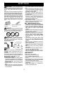
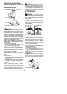
Air Filter Cover
Air Filter
Button
MUFFLER AND SPARK ARREST -
ING SCREEN
WARNING: The m uffler on th is prod-
uct contains chemicals known to the State of
California to cause cancer .
As your unitis used, carbondeposits buildup
on the m uffler and spark a rresting screen.
For normal homeowner use, however, the
mufflerand spark arresting screen will n otre-
quire any service. After 50 hours of use, we
recommend that your muffler be serviced or
replaced by your auth orized service dealer.
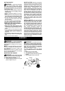
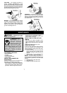
REPLACE SPARK PLUG
Replace the spark plug each year to ensure
the engine starts easier and runs better. Set
spark plug gap at 0.025 inch (0.6 mm). Igni-
tion timing is fixed and nonadjustable.
1. Twist, then pull of f spark plug boot.
2. Remove spark plug from cylinder and dis-
card .
3. Replace with Champion RCJ-6Y spark
plug and t ighten securely with a 3 /4 inch
(19 mm) socket wrench.
4. Reinstall the spark plug boot.
SERVICE AND ADJUSTMENTS
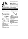
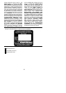
LINE REPLACEMENT
1. Remove spool by firmly pulling on tap
button.
2. Clean entire surface of hub and spool.
3. Replace with apre-wound spool, or cut two
lengths of
12-1/2 feet of 0.080″ (2 mm) di-
ameter WEED EATER brand line.
WARNING: Never use wire, rope,
string,etc.,whichcanbreak offandbecomea
dangerous missile.
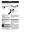
4. I nsert ends of the lines about 1/2 inch (1
cm) into the small holes on the inside of
spool.
Small
Holes
Spool
Hub
Line in Notch
Line in Notch
Line exit holes
5. W ind the line evenly and tightly onto the
spool. Wind in the direction of thearrows
found on the spool.
6. P ushthelines into thenotches, leaving 3
to 5 inches (7 -- 12 cm) unwound.
7. I nsert the lines into the the exit holes in
the hub as shown in the illustration.
8. A lign thenotches with the line exit holes.
9. P ush spool into hub until it snaps into
place.
10. Pullthelinesextendingoutsideofthehub
to release t he lines from the notches.
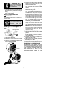
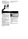
REPLACING THE CUTTING HEAD
1. Alignholeinthe dustcupwith thehole inthe
side ofthe gearboxby rotatingthe dustcup.
2. I nse rt a smal l screwdri ver int o alig n e d
holes. This will keep the shaft from turning
while removing andinstalling trimmer head.
Screwdriver
3. While holding the screwdriver in position,
removetrimmer head by turning clockwise.
4. Thread replacement trimmer head onto the
shaft by turning counterclockwise. T ighten
until secure.
5. Remove the screwdriver.
CARBURETOR ADJUSTMENT
WARNING: Keep others away when
making idlespeedadjustments. The trimmer
head will be spinning during this procedure.
Wearyour protectiveequipmentand observe
all safety precautions.
The carburetor has been carefully set at the
factory .Adjustments maybenecessary ifyou
notice any of the following conditions:
S Engine will not idl e when the throttle i s re-
leased.
Make adjustments with the unit supported so
the cutting attachment is off the ground and
will not make contact with any object. Hold
theunitby handwhilerunningandmakingad-
justments. Keep all parts of your body away
from the cutting attachment an d muf fler.