


SERVICE AND ADJUSTMENTS
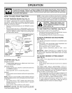
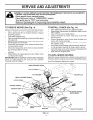
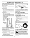
TO REPLACE MOTION DRIVE BE LT(See Fig. 20)
Park the tractor on level surface. Engage parking brake.
For assistance, there is a belt installation guide decal on
bottom side of left footrest.
BELT REMOVAL -
• Remove mower (See "TO REMOVE MOWER" in this
section of manual).
NOTE: Observe entire motion drive belt and position of all
belt guides and keepers.
• Remove belt from stationary idler and clutching idler.
• Remove belt downward from around engine pulley.
• Pull belt slack toward rear of tractor. Remove belt up-
wards from transaxle pulley by deflecting belt keepers.
• Remove belt from center span keeper and pull belt
away from tractor.
BELT INSTALLATION -
• Carefully work new belt down between transaxle belt
keepers and onto the input pulley.
• Slide belt into the center span keeper.
• Pull belt toward front of tractor and roll around the top
groove of engine pulley.
• Install belt through stationary idler and clutching idler.
• Make sure belt is in all pulley grooves and inside all
belt guides and keepers.
• Install mower (See "TO INSTALL MOWER" in this
section of manual).
ENGINE
CLUTCHING
IDLER
STATIONARY
CENTER SPAN
KEEPER
TRANSAXLE
FIG. 20
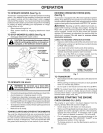
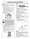
TRANSAXLE GEAR SHIFT LEVER NEUTRAL
ADJUSTMENT (See Fig. 21)
The transaxle should bein neutral when the gear shift lever is
inneutral (lockgate) position. The adjustment ispreset atthe
factory; however, ifadjustment isneeded, proceed asfollows:
• Make sure transaxle is in neutral.
NOTE: When the tractor rear wheels move freely, the
transaxle is in neutral.
• Loosen adjustment bolt infront of the right rear wheel.
• Position the gear shift lever inthe neutral position.
• Tighten adjustment bolt securely.
NOTE: Ifadditional clearance isneeded to get to adjustment
bolt, move mower deck height to the lowest position.
GEARSHIFT
NEUTRAL
LOCK
GATE
ADJ USTMENT
BOLT
FIG. 21
TO ADJUST STEERING WHEEL ALIGNMENT
If steering wheel crossbars are not horizontal (left to right)
when wheels are positioned straight forward, remove steer-
ing wheel and reassemble per instructions in the Assembly
section of this manual.
FRONT WHEEL TOE=IN/CAMBER
The front wheel toe-in and camber are not adjustable on
your tractor. If damage has occurred to affect the front
wheel toe-in or camber, contact your nearest authorized
service center/department.
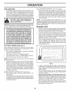
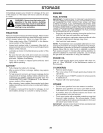
TO REMOVE WHEEL (See Fig. 22)
• Block up axle securely.
• Remove axle cover, retaining ringand washers to allow
wheel removal (rear wheel contains a square key - Do
not lose).
• Repair tire and reassemble.
• On rear wheels only: align grooves in rear wheel hub
and axle. Insert square key.
• Replace washers and snap retaining ring securely in
axle groove.
• Replace axle cover.
NOTE: Toseal tire punctures and prevent flat tires due toslow
leaks, tire sealant may be purchased from your local parts
dealer. Tire sealant also prevents tire dry rot and corrosion.
WASHERS
AXLE RETAINING
COVER RING
SQUARE KEY
(REAR WHEEL ONLY)
TO START ENGINE WITH A WEAK BATTERY
(See Fig. 23)
_ WARNING: Lead=acid batteries generate
explosive gases. Keep sparks, flame and
smoking materials away from batteries.
Always wear eye protection when around
batteries.
If your battery is too weak to start the engine, it should be
recharged. (See "BATTERY" in the Maintenance section
of this manual).
18