6
ASSEMBLY
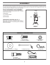
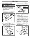
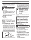
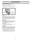
SHIFT
ROD
HAIRPIN
CLIP
SHIFT
LEVER
INDICATOR
REMOVE TILLER FROM CRATE
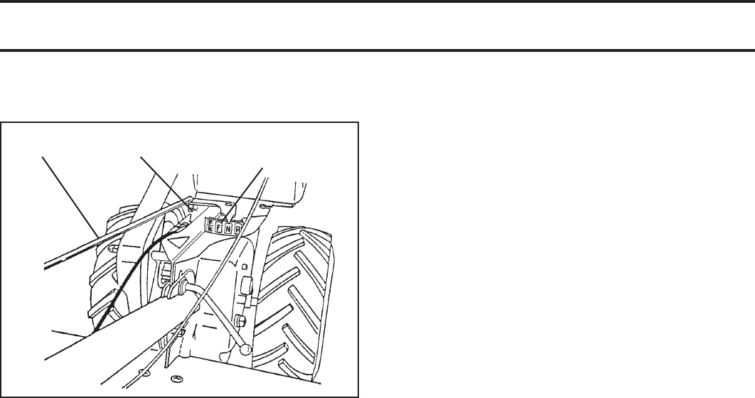
• Make sure shift lever indicator is in “N” position (See
Fig. 6)
• Tilt tiller forward by lifting handle. Separate cardboard
cover from leveling shield.
• Rotate tiller handle to the right and pull tiller out of
carton.
CONNECT SHIFT ROD (See Fig. 6)
• Insert end of shift rod into hole of shift lever indicator.
• Insert hairpin clip through hole of shift rod to secure.
Fig. 6
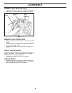
CHECK TIRE PRESSURE
The tires on your unit were overinflated at the factory for
shipping purposes. Correct and equal tire pressure is
important for best tilling performance.
• Reduce tire pressure to 20 PSI (1.4 kg/cm
2
).
HANDLE HEIGHT
• Handle height may be adjusted to better suit operator.
(See “TO ADJUST HANDLE HEIGHT” in the Service
and Adjustments section of this manual).


