


15
SERVICE AND ADJUSTMENTS
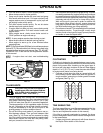
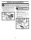
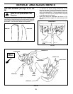
FIG. 22
SCREW
AND
WASHER
HEX NUT
AND
WASHER
(LOCATED
BEHIND
TIRE)
BELT GUARD
SCREW
AND WASHER
HAIRPIN CLIP AND
CLEVIS PIN
CABLE CLIP
SCREW
DRIVE
CONTROL
CABLE
EXTENSION
SPRING
ENGINE
PULLEY
IDLER
PULLEY
TRANS MIS SION
PULLEY
LESS
TEN SION
5/8"
MORE
TEN SION
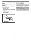
FIG. 23
TO REMOVE BELT GUARD (See Fig. 22)
NOTE: For ease of removal, remove hairpin clip and
clevis pin from left wheel. Pull wheel out from tiller about
1 inch.
• Remove two (2) screws from side of belt guard.
• Remove hex nut and washer from bottom of belt guard
(located behind wheel).
• Pull belt guard out and away from unit.
• Replace belt guard by reversing above procedure.
TO REPLACE GROUND DRIVE BELT (See
Figs. 22 and 23)
• Remove belt guard as described in “TO REMOVE BELT
GUARD”.
• Remove old belt by slipping off engine pulley fi rst then
remove from transmission pulley.
• Place new belt in groove of transmission pulley and
into engine pulley. BELT MUST BE IN GROOVE ON
TOP OF IDLER PULLEY. NOTE POSITION OF BELT
TO GUIDES.
• Check belt adjustment as described below.
• Replace belt guard.
• Reposition wheel and replace clevis pin and hairpin
clip.
GROUND DRIVE BELT ADJUSTMENT (See
Fig. 23)
For proper belt tension, the extension spring should have
about 5/8 inch (16 mm) stretch when drive control bar is
in “EN GAGED” position. This tension can be attained as
fol lows:
• Loosen cable clip screw securing the drive control
cable.
• Slide cable forward for less tension and rearward for
more tension until about 5/8 inch (16 mm) stretch is
obtained while the drive control bar is engaged.
• Tighten cable clip screw securely.