


7
ASSEMBLY
WARNING: If received assembled,
repeat allsteps toensure your unitis properly
assembled and all fasteners are secure.
Examine parts for dam age. Do not use dam-
aged parts.
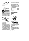
NOTE: If you need assistance or find parts
missing or damaged, call 1-800-554-6723.
It is normal for the fuel filter to rattle in the
empty fuel tank.
Finding fuel oroil residue on m uffler is nor m al
due to carburetor adjustments and testing
done by the manufacturer.
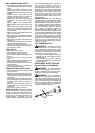
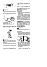
INSTALLING TRIMMER ATTACH -
MENT
CAUTION:
When installing trimmer a ttach-
ment, placethe unitona flatsurfacefor stabil-
ity.
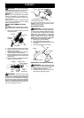
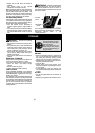
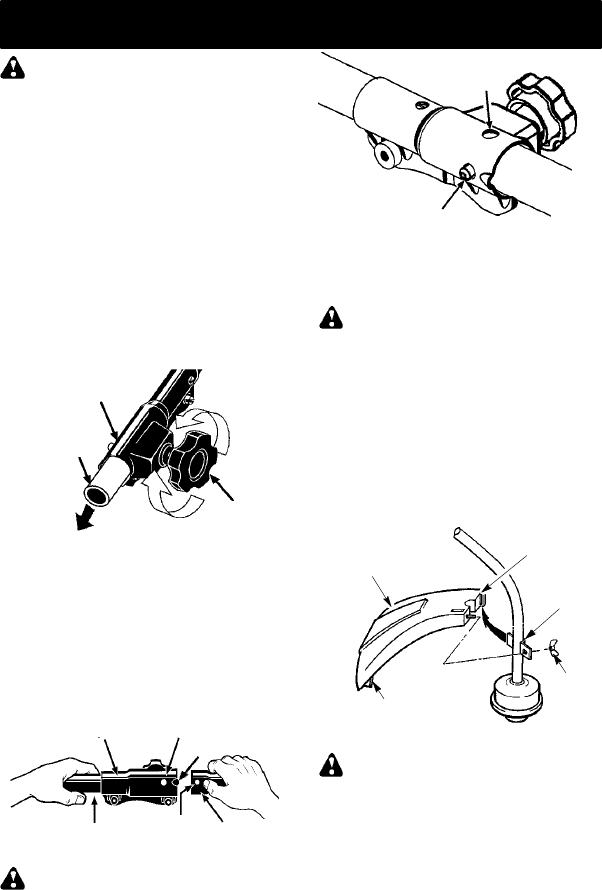
1. Loosen the coupler by turning the knob
counterclockwise.
Coupler
Knob
LOOSEN
TIGHTEN
Shipping
protector
2. Remove shipping protector from coupler.
3. Remove the shaft cap from t he trimmer
attachment (if present).
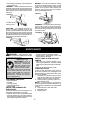
4. Position locking/release button ofattach-
ment into guide recess of coupler .
5. Push theattachment intothecoupleruntil
the locking/release button snaps into the
primary hole.
6. Before usingtheunit, tightenthe knobse-
curely by turning clockwise.
Coupler Primary Hole
Upper
Shaft
Locking/
Release
Button
Lower
Attachment
Guide Recess
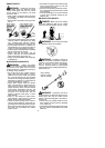
WARNING: Make sure the locking/
release button is locked in the primary hole
and theknob is securely tightened before op -
erating the unit. Al l atta c hment s ar e designed
to be used in the primary hole unless otherwise
stated in the applicable attachment instruction
manual. Using the wronghole could l ead toseri-
ous injury or damage to the unit.
Locking/Release
Button in Primary Hole
Secondary Hole
For optional attachments, see the AS-
SEMBL Y section of the applicable attach-
ment instruction manual.
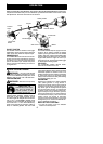
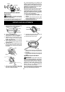
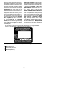
ATTACHING SHIELD
WARNING: The shield must be prop-
erly installed. Th e shieldprovides partial p rotec-
tion from the risk of thrown objects to the opera-
tor and others and is equipped with a line limiter
blade which cuts excess l ine to t he proper
length. The line limiter blade (on underside of
shield) is sharp and can cut you. For proper
orientatio n of shield, see KNOW YOUR TRIM-
MER illustration in OPERATION section.
1. Remove wing nut from shield.
2. Insert bracket into slot as shown.
3. Pivot shielduntilboltpasses th roughhole
in bracket.
4. Securely tighten wing nut onto bolt.
Slot
Shield
Wing
Nut
Bracket
Line Limiter Blade
ADJUSTING THE ASSIST HANDLE
WARNING: When adjusting the assist
handle, besureit r emains above the safety label
and below the mark or arrow on the shaft.
1. Loosen wing nut on handle.
2. Rotate the handle on the shaft to a n up-
right position; retighten wing nut.