


-- 3 --
D
Disconnect spark plug before performing
maintenance except for carburetor adjust-
ments.
D
Use only recommended Poulan PRO
!
re-
placement parts; use of any other parts
mayvoidyourwarrantyandcausedamage
to your unit.
D
Empty fue l ta nk before storing th e unit. Use
upfuelleftincarburetor bystartingengineand
letting it run until it stops .
D
Do not use any accessory o r attachment
other than those recommended by manufac-
turer for use with your unit.
D
Donotstoretheunitorfuel inaclosedarea
where fuel vapors can reach sparks or an
openflamefrom hotwaterheaters,electric
motors or switches, furnaces, etc.
D
Storein a dry areaout of reach ofchildren.
SPECIAL NOTICE:
Your blower is
equipped with a temperature limiting muffler
and spark a rresting screen which meets the
requirements of California Codes 4442 and
4443. All U.S. forest land and the states of
California, Idaho, Maine, Minnesota, New
Jersey, Oregon, and Washington require by
lawthatmanyinternalcombustionenginesbe
equippedwithasparkarrestorscreen. Ifyou
operate a blower in a state or locale where
such regulations exist, you are legally re-
sponsibleformaintainingtheoperatingcondi-
tionof theseparts. Failure todo sois a viola-
tion of the law.
SAFETYNOTICE:
Exposure tovibrations
through prolonged use of gasoline powered
handtoolscouldcausebloodvessel ornerve
damage in the fingers, hands, and joints of
people prone to circulation disorders o r ab-
normal swelling. Prolonged use in cold
weatherhasbeenlinkedtobloodvesseldam-
ageinotherwisehealthypeople.Ifsymptoms
occur such as numbness, pain, loss of
strength, change in skin color or texture, or
loss offeeling in the fingers,hands, or joints,
discontinue the u se of this tool and s eek
medical attention. An antivibration system
does not guarantee the avoidance of these
problems.Users who operatepowertools on
a continual and regular basis must monitor
closelytheirphysical conditionandthecondi-
tion of this tool .
ASSEMBLY
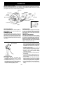
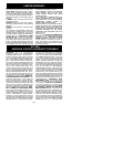
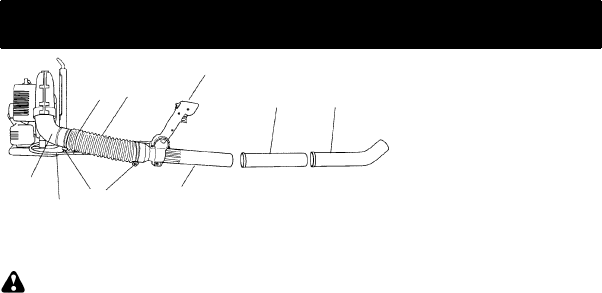
CARTON CONTENTS
1. Outlet Tube
2. Flexible Tube
3. HoseClamps
4. Control Handle
5. Base Tube
6. Middle T ube
7. Air Nozzle
8. ThrottleCable
9. ThrottleCable Clamp
1
2
3
5
6
4
7
8
9
W ARNING:
If you receive your unit
assembled, check each step to insure your
unit is properly assembled and all fasteners
are secure. Follow all safety information in
the manual and on the unit.
1. Locate and identify all components.
2. Connecttheflexibletubetotheoutlettube
on the engine. T ighten the hose clamp.
3. Remove bottom screw from control han-
dle. Install the control handle against the
flared areaon thebase tubewith theON/
STOP switch facing the engine.
4. Connectthebasetubetotheflexibletube.
T ighten the hose clamp.
5. Assemble the air nozzle to the middle
tube and connect the as sembly to the
base tube by pushing the tubes together
and turning them until they lock in place.
6. Removethrottlecableclamp fromflexible
tube. Placethrottlecableinclampandre-
install on flexible tube.