4
ASSEMBLY
CARTON CONTENTS
Check carton contents for the following:
S
Brushcutter
S
tube mounting screws (2)
S
tube mounting nuts (2)
S
control handle mounting screw (1)
S
blade shield screws (4)
S
handlebar screws (2)
S
cupped washer (1)
S
large nut for installing blade (1)
S
long hex key wrench (1)
S
short hex key wrench (1)
S
bracket cover
S
shield for use with blades
S
shield for use with trimmer head
S
semi-automatic trimmer head
S
shoulder strap with warning
S
brush blade
S
handlebar
S
container of oil
Examine parts for damage. Do not use dam-
aged parts.
NOTE:
If you need assistance or find that
parts are missing or damaged, call
1-800-554-6723.
It is normal for the fuel filter to rattle in the
empty fuel tank.
Finding fuel or oil residue on m uffler is normal
due to carburetor adjustments and testing
done by t he manufacturer.
ASSEMBLY
WARNING:
If received assembled,
repeat all steps to ensure your unit is properly
assembled and all fasteners are secure.
TOOLS REQUIRED
S
2 hex key wrenches (provided)
S
adjustable wrench or large pliers
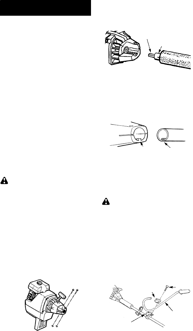
ATTACHING THE TUBE
NOTE:
Illustr a tion swithin thissection willhelp
in identifying the assembly steps. Be sure to
rea d eac h sec tion and r ev ie w th e illustrations ,
before y ou begin.
NOTE:
A drive shaft is located in the center
of the tube. Make sure this shaft does not fall
out of the tube. Dirt on the shaft will signifi-
cantly reduce the life of the unit. If this shaft
falls out, clean, relubricate , and re-install.
S
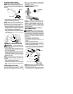
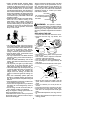
Insert the 2tube assembly screws andnuts
as illustrated. Keep loose at this t ime, you
will tighten them during a l ater step.
S
Some units may include a plastic cover
overthe endofthe tube. Ifyour unit includes
any covering, remove the coverat thistime.
S
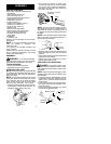
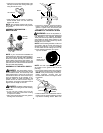
Pull about 1/2 inch of the drive shaft out of
the inside of the tube.
Pull about 1/2 inch
from tube
Tube
NOTE:
The end of the drive shaft is square.
This square end fits inside a square hole in a
shaft inside the engine. Look inside the end of
the engine and you will see the square hole in
the shaft.
NOTE:
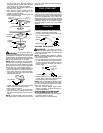
The endof the tube hasagroove t hat
aligns with a ridge in the engine opening. Lo-
cate the groove and ridge.
GrooveRidge
S
Align the groove in the tube with the ridge in
the engi ne opening. Insert the tube into the
opening.
S
Firmly push t he tube into engine until it will no
longer go into the openi ng.
S
Tighten the screws, using one of the hex
keys provided with the unit.
ATTACHING THE HANDLEBAR
DANGER:
The barrier portion of the
handlebar must be installed as shown to pro-
vide a barrier between operator and the spin-
ning blade.
NOTE:
Unlike abicycle the handgri ps on the
handlebar point toward the front instead ofto-
ward the back.
S
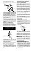
Locate the decal on the handlebar. This de-
cal includes two arrows. Position the han-
dlebar on the mounting b racket between
these arrows.
S
Position the bracket cover over the handl e-
bar. A gain make sure the handlebar is be-
tween the arrows.
S
Insert screws and hand tighten only. These
screws will be tightened later.
Bracket Cover
Screw
Mounting
Bracket
Handlebar


