


5
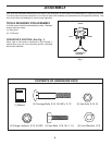
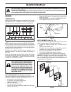
ASSEMBLY
d
e
pth_
st
a
k
e_
4
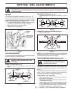
Hex Bolts, Lock Wash ers, and hex Nuts
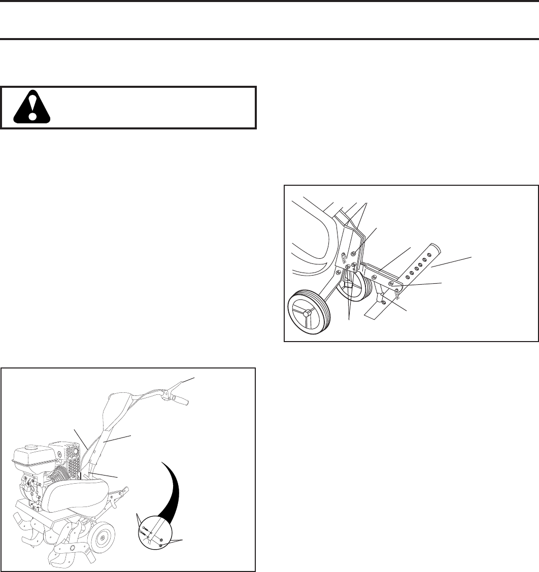
Support Bolt
Depth Stake Support
Engine Bracket Halves
Nut “A”
Depth
Stake
Stake Spring
Tine
Con trol
Cable
Handle
Mount
Handle
Column
Tine Con trol
Flange
Lock nut
Carriage
Bolt
Fig. 1
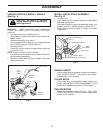
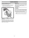
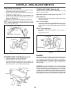
INSTALL DEPTH STAKE ASSEMBLY
(See Fig. 2)
• Loosen nut “A”.
• Insert stake support between engine bracket halves
with stake spring down.
• Bolt stake support to engine brackets with bolts, lock
washers and nuts. Tighten se curely. Tighten nut “A”.
• Depth stake must move freely. If it does not, loosen
support bolt.
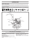
UNPACK CARTON & INSTALL HANDLE
(See Fig. 1)
CAUTION: Be careful of exposed
sta ples when handling or disposing of
cartoning material.
IMPORTANT: WHEN UNPACKING AND AS SEM BLING
TILLER, BE CAREFUL NOT TO STRETCH OR KINK
CABLE(S).
• Cut cable ties securing handle column.
• Route cable(s) as shown and slide handle column onto
handle mount.
• Remove all packing from carton.
• Secure handle column using two (2) carriage bolts and
two (2) flange locknuts. Tighten se cure ly.
• Cut away carton.
• Route tine control cable(s) through plas tic cable clip
on handle mount.
NOTE: Cables must not touch the muffler.
• Cut cable ties securing tiller to skid. Re move tiller from
skid by pulling backwards.
• Remove screws securing depth stake to skid and
discard the screws.
HANDLE HEIGHT
• Handle height may be adjusted to better suit operator.
(See “HANDLE HEIGHT” in the Service and Ad just-
ments section of this manual).
TILLING WIDTH
• Tilling width may be adjusted to better handle your
tilling con di tions (See “TINE ARRANGEMENT” in the
Ser vice and Adjustments section of this manual).
TINE OPERATION
• Check tine operation before first use. (See “TINE
OPERATION CHECK” in the Service and Adjustments
section of this manual).
Fig. 2