


5
1
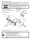
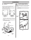
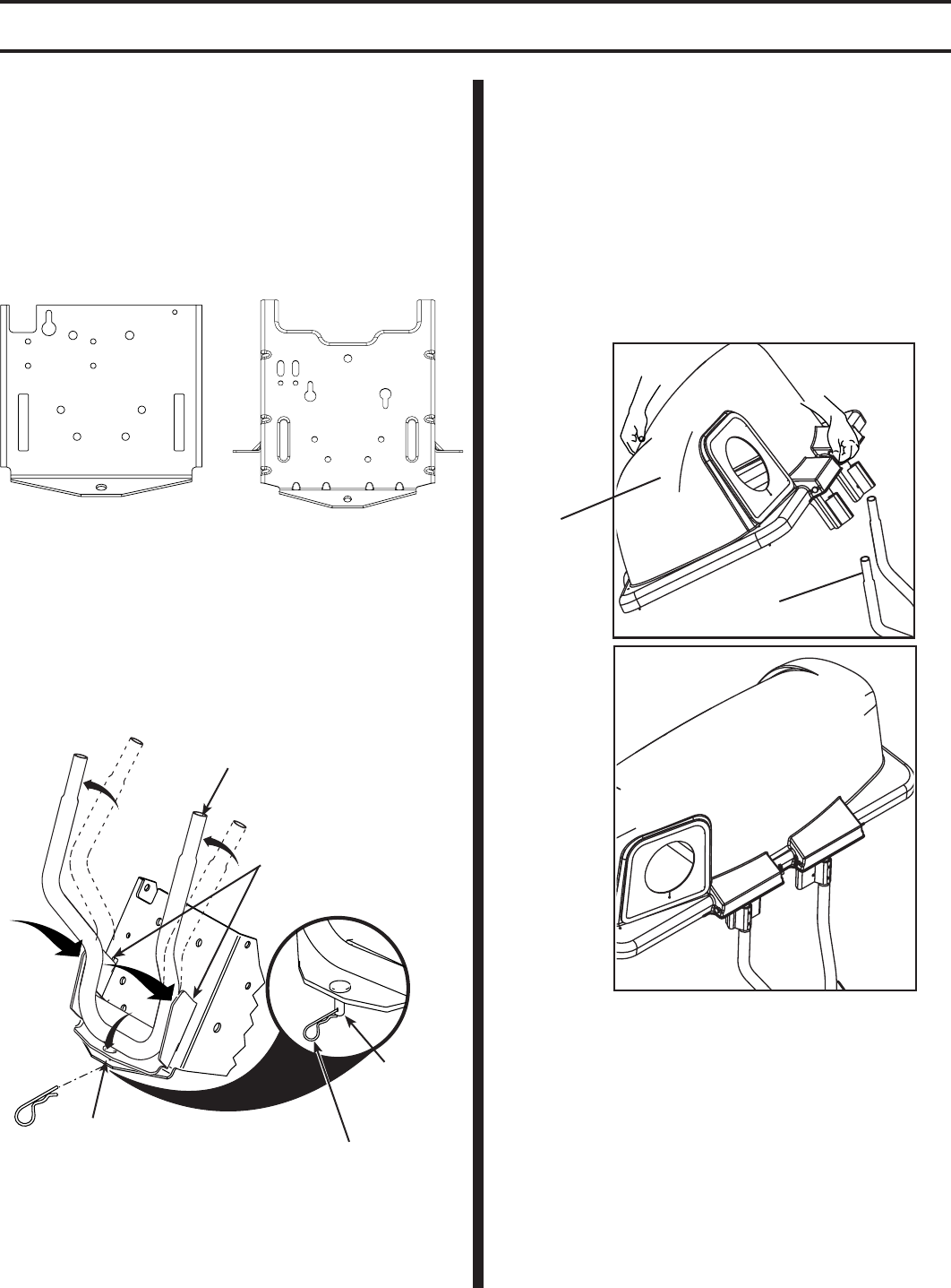
BAGGER SUPPORT ASSEMBLY
(See Fig. 1)
Determine the correct support assembly for your tractor.
The support assemblies are marked "A" and "B".
Compare the drawbar illustrations below to the drawbar
located at the rear of your tractor.
Use the support assembly indicated for your tractor and
discard the other support assembly.
2
FIG. 1
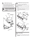
MOUNTING COVER ASSEMBLY TO
SUPPORT ASSEMBLY (See Fig. 2)
NOTE: For ease of assembly, you may wish to obtain the
as sis tance of another person for mounting cover assembly
to tractor.
1. Position cover assembly on ground behind tractor.
2. Lift and rotate cover to align cover brackets with support
assembly tubes.
3. Slide cover assembly down onto the support tubes.
FIG. 2
03024
COVER
ASSEMBLY
SUPPORT
ASSEMBLY
ASSEMBLY
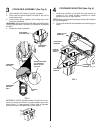
1. Slide fl anges of support assembly into drawbar slots
fi rst, then, pivot backwards inserting pin into drawbar
pin hole.
2. Be sure support assembly is seated properly, then
secure with retainer spring.
DRAWBAR A
Use Support Assembly
Marked "A"
DRAWBAR B
Use Support Assembly
Marked "B"
0254
3
INSERT
FLANGES
FIRST INTO
DRAWBAR
SLOTS
SUPPORT
ASSEMBLY
DRAWBAR SLOTS
RETAINER
SPRING
PIN
020
51
0
2
051
02051
DRAWBAR
PIN HOLE