


22
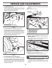
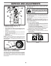
TO REPLACE MOTION DRIVE BELT
(See Fig. 37)
Park the tractor on level surface. En gage parking brake.
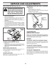
For as sis tance, there is a belt installation guide decal on
bottom side of left footrest.
BELT REMOVAL -
1. Remove mower (See “TO REMOVE MOWER” section
in this manual).
NOTE: Observe entire motion drive belt and position of all
belt guides and keepers.
2. Disconnect clutch wire harness (A).
3. Remove anti-rotation link (B) on right side of tractor.
4. Remove belt from stationary idler (C) and clutching idler (D).
5. Remove belt from centerspan idler (E).
6. Pull belt slack toward rear of trac tor. Carefully remove
belt up wards from trans mis sion input pulley and over
cooling fan blades (F).
7. Remove belt downward from engine pulley and around
electric clutch (G).
8. Slide belt toward rear of tractor, off the steering plate
(H) and remove from tractor.
BELT INSTALLATION -
1. Install new belt from tractor rear to front, over the steer-
ing plate (H) and above clutch brake pedal shaft (J).
2. Pull belt toward front of tractor and roll belt around
electric clutch and onto engine pulley (G).
3. Pull belt toward rear of tractor. Carefully work belt down
around transmission cooling fan and onto the input pul-
ley (F). Be sure belt is inside the belt keeper.
4. Install belt on centerspan idler (E).
5. Install belt through stationary idler (C) and clutch ing idler (D).
6. Reinstall anti-rotation link (B) on right side of tractor.
Tighten securely.
7. Reconnect clutch harness (A).
8. Make sure belt is in all pulley grooves and in side all belt
guides and keep ers.
9. Install mower (See “TO INSTALL MOWER” section in
this manual).
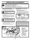
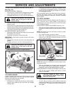
FRONT-TO-BACK ADJUSTMENT (See Figs. 35 & 36)
IMPORTANT: Deck must be level side-to-side.
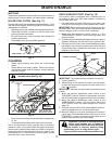
To obtain the best cutting re sults, the mower blades should
be adjusted so the front tip is 1/8" to 1/2" lower than the
rear tip when the mower is in its highest position.
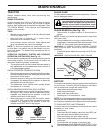
CAUTION: Blades are sharp. Protect
your hands with gloves and/or wrap
blade with heavy cloth.
• Raise mower to highest position.
• Position any blade so the tip is pointing straight forward.
Measure distance (B) to the ground at front and rear tip
of the blade.
Fig. 34
NOTE: Each full turn of the adjustment nut will change
mower height about 1/8".
• Recheck measurements, adjust if necessary until front
tip of blade is 1/8" to 1/2" lower than the rear tip.
• Hold adjustment nut in position with wrench and tighten
jam nut securely against adjustment nut.
B
B
Fig. 35
Fig. 36
02966
A A
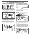
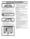
• If adjustment is necessary, see steps in Visual Adjust-
ment instructions above.
• Recheck measurements, adjust if necessary until both
sides are equal.
B
02950
A
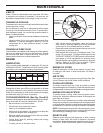
TIGHTEN ADJUST
NUT B TO RAISE
MOWER
LOOSEN
ADJUST NUT
B TO LOWER
MOWER
LOOSEN JAM NUT A FIRST
• If front tip of blade is not 1/8" to 1/2" lower than the rear
tip, go to the front of tractor.
• With an 11/16" or adjustable wrench, loosen jam nut A
several turns to clear adjustment nut B.
• With a 3/4" or adjustable wrench, turn front link adjustment
nut (B) clockwise (tighten) to raise the front of mower,
or, counterclockwise (loosen) to lower the front mower.
SERVICE AND ADJUSTMENTS