


23
SERVICE AND ADJUSTMENTS
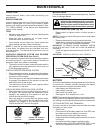
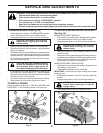
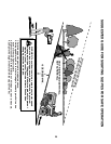
TO REPLACE MOTION DRIVE BELT
(See Fig. 39)
Park the tractor on level surface. En gage parking brake.
For as sis tance, there is a belt installation guide decal on
bottom side of left footrest.
BELT REMOVAL -
1. Remove mower (See “TO REMOVE MOWER” section
in this manual).
NOTE: Observe entire motion drive belt and position of all
belt guides and keepers.
2. Disconnect clutch wire harness (A).
3. Remove anti-rotation link (B) on right side of tractor.
4. Remove belt from stationary idler (C) and clutching idler (D).
5. Remove belt from centerspan idler (E).
6. Pull belt slack toward rear of trac tor. Carefully remove
belt up wards from trans mis sion input pulley and over
cooling fan blades (F).
7. Remove belt downward from engine pulley and around
electric clutch (G).
8. Slide belt toward rear of tractor, off the steering plate
(H) and remove from tractor.
BELT INSTALLATION -
1. Install new belt from tractor rear to front, over the steer-
ing plate (H) and above clutch brake pedal shaft (J).
2. Pull belt toward front of tractor and roll belt around
electric clutch and onto engine pulley (G).
3. Pull belt toward rear of tractor. Carefully work belt down
around transmission cooling fan and onto the input pul-
ley (F). Be sure belt is inside the belt keeper.
4. Install belt on centerspan idler (E).
5. Install belt through stationary idler (C) and clutch ing idler (D).
6. Reinstall anti-rotation link (B) on right side of tractor.
Tighten securely.
7. Reconnect clutch harness (A).
8. Make sure belt is in all pulley grooves and in side all belt
guides and keep ers.
9. Install mower (See “TO INSTALL MOWER” section in
this manual).
electric
02953
E
A
F
B
J
G
C
H
D
Fig. 39
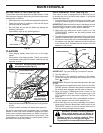
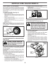
TO CHECK BRAKE
If tractor requires more than five (5) feet to stop at highest
speed in high est gear on a level, dry concrete or paved
surface, then brake must be serviced.
You may also check brake by:
1. Park tractor on a level, dry concrete or paved surface,
depress brake pedal all the way down and engage
parking brake.
2. Disengage transmission by placing freewheel control
in “transmission disengaged” position. Pull freewheel
control out and into the slot and release so it is held in
the disengaged position.
The rear wheels must lock and skid when you try to manu-
ally push the tractor forward. If the rear wheels rotate,
then the brake needs to be serviced. Contact a qualified
service center.
Fig. 40
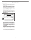
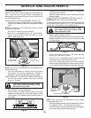
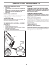
TRANSAXLE MOTION CONTROL LEVER
NEUTRAL ADJUSTMENT (See Fig. 40)
The motion control lever has been pre set at the factory
and adjustment should not be necessary.
• Loosen adjustment bolt in front of the right rear wheel,
and lightly tighten.
• Start engine and move motion control lever until tractor
does not move forward or backward.
• Hold motion control lever in that position and turn engine
off.
• While holding motion control lever in place, loosen the
adjustment bolt.
• Move motion control lever to the neutral (lock gate) position.
• Tighten adjustment bolt securely.
NOTE: If additional clearance is needed to get to ad just ment
bolt, move mower deck height to the lowest position.
After above adjustment is made, if the tractor still creeps
forward or backward while motion control lever is in neutral
position, follow these steps:
• Loosen the adjustment bolt.
• Move the motion control lever 1/4" to 1/2" in the direc-
tion it is trying to creep.
• Tighten adjustment bolt securely.
• Start engine and test.
• If tractor still creeps, repeat above steps until satisfied.
ADJUSTMENT
BOLT
NEUTRAL
LOCK
GATE
MOTION CONTROL
LEVER