


23
02537
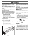
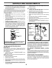
• Disengage transmission by placing freewheel control
in “transmission disengaged” position. Pull freewheel
con trol out and into the slot and release so it is held in
the disengaged position.
The rear wheels must lock and skid when you try to manually
push the tractor forward. If the rear wheels rotate, the brake
needs to be adjusted or the pads need to be replaced.
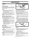
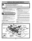
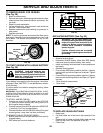
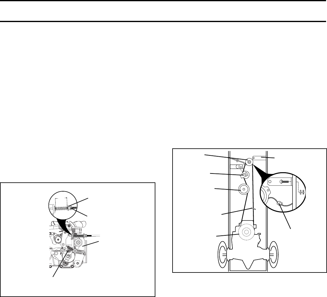
TO ADJUST BRAKE
• Depress brake pedal all the way down and en gage
parking brake.
• Measure distance between brake operating arm and
nut “A” on brake rod.
• If distance is other than 1-3/4", loosen jam nut and turn
nut “A” until distance becomes 1-3/4". Retighten jam
nut against nut “A”.
• Engage transmission by placing freewheel control in
“trans mis sion engaged” position.
• Road test tractor for proper stopping distance as stated
above. Readjust if nec es sary. If stopping distance is
still greater than fi ve (5) feet in high est gear, further
main te nance is nec es sary. Replace brake pads or
contact a qualifi ed service center.
TRANSMISSION REMOVAL/RE PLACE MENT
Should your transmission require removal for service or
replacement, it should be purged after reinstallation and
before operating the tractor. See “PURGE TRANS MIS SION”
in the Operation section of this manual.
SERVICE AND ADJUSTMENTS
TO AD JUST STEER ING WHEEL ALIGN-
MENT
If steering wheel crossbars are not horizontal (left to right)
when wheels are positioned straight forward, remove steer-
ing wheel and reassemble per instructions in the Assembly
section of this manual.
FRONT WHEEL TOE-IN/CAMBER
The front wheel toe-in and camber are not adjustable on
your tractor. If damage has occurred to affect the front
wheel toe-in or camber, contact your nearest authorized
service center/department.
FIG. 26
WITH PARKING BRAKE “ENGAGED”
JAM NUT
DO NOT TOUCH THIS NUT. IF FURTHER BRAKE AD JUST MENT
IS NECESSARY CONTACT YOUR NEAR EST AUTHORIZED
SERVICE CENTER/DEPARTMENT
OPERATING
ARM
NUT “A”
1-3/4"
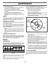
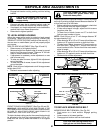
FIG. 27
01511
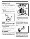
CLUTCH LOCATOR
CLUTCH
WIRE
HAR NESS
STATIONARY
IDLER
TRANS MIS SION
INPUT PULLEY
CLUTCH ING
IDLER
ELECTRIC
CLUTCH
TO REPLACE MOTION DRIVE BELT
(See Fig. 27)
Park the tractor on level surface. En gage parking brake.
For as sis tance, there is a belt installation guide decal on
bottom side of left footrest.
BELT REMOVAL -
• Remove mower (See “TO RE MOVE MOWER” in this
section of manual).
NOTE: Observe entire motion drive belt and position of all
belt guides and keepers.
• Disconnect clutch wire harness.
• Remove clutch locator.
• Remove belt from stationary idler and clutching idler.
• Remove belt downward from engine pulley and around
electric clutch.
• Pull belt slack toward rear of trac tor. Carefully remove
belt up wards from trans mis sion input pulley and over
cooling fan blades.
CENTER SPAN
KEEPER
• Remove belt from center span keeper and pull belt
away from tractor.
BELT INSTALLATION -
• Carefully work new belt down around transmission
cool ing fan and onto the input pulley.
• Slide belt into the center span keeper.
• Pull belt toward front of tractor and roll belt around
electric clutch and onto engine pulley.
• Install belt through stationary idler and clutch ing
idler.
• Reinstall clutch locator and tighten nut securely.
• Reconnect clutch harness.
• Make sure belt is in all pulley grooves and in side all
belt guides and keep ers.
• Install mower (See “TO IN STALL MOWER” in this sec-
tion of manual).