


6
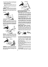
SPECIAL NOTICE: This unit is equipped
with a temperature limiting muffler and spark
arresting screen which meets the require-
ments o fCalifornia Codes 4442and4443. All
U.S. forest land and the states of California,
Idaho, Maine, Minnesota, New Jersey, Ore-
gon, and Washington require by law that
many internal combustion engines be
equippedwithasparkarrestingscreen. Ifyou
operateinalocalewheresuch regulationsex-
ist, youare legallyresponsibleformaintaining
theoperatingconditionof theseparts. Failure
to do so is a violation of the law. For normal
homeowner use,the mu fflerandsparkarrest-
ing screen will not req uire any service. After
50 hours of use, we recommend that your
mufflerbeservicedorreplacedby yourautho-
rized service dealer.
ASSEMBLY
CARTON CONTENTS
Check carton conte nts against t he foll owinglist:
S Powerhead
S Attachment (with trimm er head installed)
S Cupped washer
S Large nut for installing blades
S Hex wrench
S Handlebar
S Bracket cover
S Bracket cover screws (2)
S Metal blade shield
S Blade shield screws (4)
S 4--point weed blade
S Plastic shield
S Wing nut (screwed onto plastic shield)
S Shoulder strap with warning
S Container of oil
WARNING: Alwaysstopunit anddis-
connectspark plugbefore performinganyas-
sembly procedures.
WARNING: If received assembled,
repeat allsteps toensure your unit isproperly
assembled and all fasteners are secure.
Examine parts for damage. Do not use dam-
aged parts.
NOTE: If you need assistance or find parts
missing or damaged, call 1-800-554-6723.
It is normal for the fuel filter to rattle in the
empty fuel tank.
Finding fuelor oil residue on muffler isnormal
due to carburetor adjustments and testing
done by the manufacturer .
TOOLS REQUIRED
S Hex wrench (provided)
S Adjustable wrench
S Phillips screwdriver
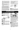
INSTALLING BRUSHCUTTER
ATTACHMENT
CAUTION:
When installing brushcutter at-
tachment, place the unit on a flat surface for
stability.
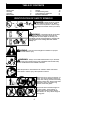
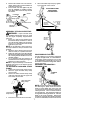
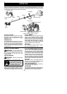
1. Loosen the coupler by turning the knob
counterclockwise.
Coupler
Knob
LOOSEN
TIGHTEN
Shipping
protector
2. Remove shipping protector fromcoupler .
3. Remove the shaft cap from thebrushcutter
attachment (if present).
4. Position locking/release button o fattach-
ment into guide recess of coupler.
5. Pushthe a ttachmentintothe coupleruntil
the locking/release button snaps into the
primary hole.
6. Before using the unit, tighten the knob se-
curely by turning clockwise.
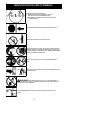
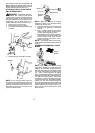
Coupler
Primary Hole
Upper
Shaft
Locking/
Release
Button
Attachment
Guide Recess
WARNING: Make sure the locking/
release button is locked in the primary hole
and theknob is securely tightened before op-
erating the unit.Allattachments aredesigned
to be used in the primary hole unless other-
wise stated in the applicable attachment in-
struction manual. Using the wrong holecould
lead to serious injury or d amage to the unit.
Locking/Release
Button in Primary Hole
For assembly of optional attachments (see
list on page 11 ), refer to the ASSEMBLYsec-
tion of the applicable attachment in struction
manual.
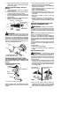
ATTACHING THE HANDLEBAR
DANGER: To avoid serious injury, the
barrierportion ofthe handlebar m ust beinstalled
as shown to provide a barrier between operator
and the spinning blade.
1. Locate the decal on the handlebar. This
decal includes an arrow. Position the
handlebar with the mounting bracket at
the end of the arrow.