


11
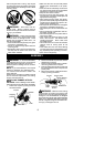
4. Pull starter rope handle sharply until en-
gine starts and runs.
5. Allow unit to run for 10--15 seconds, then
fully squeeze the throttle trigger to disen-
gage the starting system.
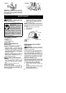
STARTING A WARM ENGINE
1. Squeeze and hold the throttle trigger.
Keep throttle trigger fully squeezed until
engine runs smoothly.
2. Pull starter rope sharply while squeezing
throttle trigger until engine runs.
NOTE: Normally , the warm starting proce-
dure can be used within 5--10 minutes after
the unit is turned off. If the unit sits for more
than 10 minutes without being ran, it will be
necessary to start the unit by following the
steps under ST AR TING A COLD ENGINE or
following the starting instruction steps shown
on the unit.
START ING A FLOODED ENGINE
Flooded engines can be started by placing
the start lever to the RUN position. Fully
squeeze throttle trigger. Pull the starter han-
dle repeatedly whilesqueezing throttletrigger
until engine starts and runs. This could re-
quire pulling the starter handle many times,
depending on how badly the unit is flooded.
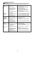
If the unit still doesn’t start, refer to
TROUBLESHOOTING TABLE or call
1-800-554-6723.
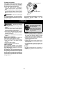
OPERATING THE COUPLER
This model is equipped with a coupler which
enables optional attachments to be installed.
The optional attachments are:
MODEL:
Edger PP1000E......................
Cultivator PP2000T...................
Blower PP3000B.....................
Brushcutter PP4000C.................
Pruner PP5000P.....................
WARNING: Always s topunitand dis -
connect spark plug bef oreremoving or ins tal-
ling a ttachments.
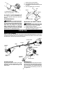
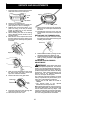
REMOVING TRIMMER ATTACH-
MENT (OR OTHER OPTIONAL AT -
TACHMENTS)
CAUTION:
When removing or installing at-
tachments, place the unit on aflat surface for
stability.
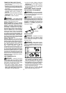
1. Loosen the coupler by turning the knob
counterclockwise.
Coupler
Knob
LOOSEN
TIGHTEN
Upper Shaft
Attachment
2. Press and hold the locking/release button.
L
ocking
/
Release
Button
Coupler
Upper Shaft
Attachment
3. While securely holding the engine and
upper shaft, pull the a ttachment straight
out of the coupler.
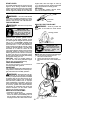
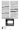
INSTALLING OPTIONAL ATTACH-
MENTS
1. Remove the shaft cap from the a ttach-
ment (if p resent).
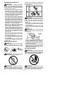
2. Position locking/release button of attach-
ment into guide recess of coupler .
3. Push theattachmentinto the c oupleruntil
the locking/release button snaps into the
primary hole.
4. Before usingtheunit, tightenthe k nobse-
curely by turning clockwise.
Coupler Primary Hole
Upper
Shaft
Locking/
Release
Button
Attachment
Guide Recess
WARNING: Make sure the locking/
release button i s locked in the primary hole
and the knob is s ecurely tightened before op-
erating the unit. Al l atta chment s are des igned
to be used in the primary hole unless otherwise
stated in the applicable attachment instruction
manual. Using t he wrong h ole could l ead toseri-
ous injury or dam age to the unit.
Locking/Release
Button in Primary Hole
OPERATING INSTRUCTIONS
It is recommended that the engine not be
operated for longer than 1 minute at full
throttle.