


10
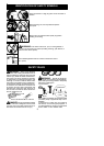
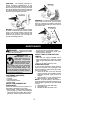
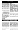
Air Filter Cover
Air Filter
Button
MUFFLER AND SPARK ARREST-
ING SCREEN
WARNING: The muffler on this prod-
uct contains chemicals known to the State o f
California to cause cancer .
As yourunit isused,carbondepositsbuildup
on the muffler and spark arresting screen.
For normal homeowner use, however, the
mufflerandspark arresting screen willnotre-
quire any service. After 50 hours of use, we
recommend that your muffler be serviced or
replaced by your authorized service dealer.
REPLACE SPARK PLUG
Replace the spark plug each year to ensure
the engine starts easier and runs better. Set
spark plug gap at 0.025 inch (0.6 mm). Igni-
tion timing is fixed and nonadjustable.
1. T wist, then pull of f spark plug boot.
2. Remove spark plug from cylinder and dis-
card .
3. Replace with Champion RCJ-6Y spark
plug and tighten securely with a 3/4 inch
(19 mm) socket wrench.
4. Reinstall the spark plug boot.
SERVICE AND ADJUSTMENTS
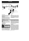
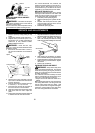
LINE REPLACEMENT
1. Remove spool by firmly pulling on tap
button.
2. Clean entire surface of hub and spool.
3. Replace with a pre-wound spool, or cut
two lengths of
12-1/2 feet(3.8 meters)of
0.080 inch (2 mm) diameter Poulan/
WEED EATER brand line.
WARNING: Never use wire, rope,
string,etc.,whichcanbreakoffandbecomea
dangerous missile.
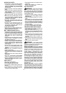
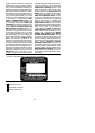
4. Insert ends of the lines about 1/2 inch ( 1
cm) into the small holes on the inside of
spool.
Small
Holes
Spool
Hub
Line in Notch
Line in Notch
Line exit holes
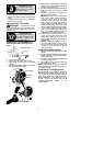
5. Wind the line evenly and tightly onto the
spool. Wind inthe directionof thearrows
found on the spool.
6. Pushthe linesintothenotches,leaving3
to 5 inches (7 -- 12 cm) unwound.
7. Insert the lines into the the exit holes in
the hub as shown in the illustration.
8. Alignthe notches with theline exit holes.
9. Push spool into hub until it snaps into
place.
10. Pullthelinesextendingoutsideofthehub
to release the lines from the notches.
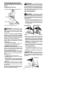
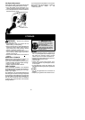
REPLACING THE CUTTING HEAD
1. Alignholeinthedustcupwith theholeinthe
side ofthegearboxby rotatingthedustcup.
2. I n se rt a smal l screwdri ver int o alig n e d
holes. This will keep the shaft from turning
while removingandinstalling trimmerhead.
Screwdriver
3. While holding the screwdriver in position,
removetrimmer headby turning clockwise.
4. Thread replacement trimmer head ontothe
shaft by t urning counterclockwise. Tighten
until secure.
5. Remove the screwdriver .
CARBURETOR ADJUSTMENT
WARNING: Keep othersaway when
making idlespeedadjustments. Thetrimmer
head will be spinning during this pr ocedure.
Wearyour protectiveequipmentandobserve
all safety precautions.
The carburetor has been carefully set a t the
factory .Adjustmentsmaybenecessaryifyou
notice a ny of the following conditions:
S Engine will not idl e when the throttle i s re-
leased.
Make adjustments with the unitsupported so
the cutting attachment is off the ground and
will not make contact with any object. Hold
theunitbyhandwhilerunningandmakingad-
justments. Keep all parts of your body away
from the cutting attachment an d m uffler.