


4
equippedwithasparkarresting screen. Ifyou
operateinalocalewheresuchregulationsex-
ist, youare legallyresponsibleformaintaining
theoperating conditionof theseparts. Failure
to do so is a violation of the law. For normal
homeowner use,the mu fflerandsparkarrest-
ing screen will not require any service. After
50 hours of use, we recommend that your
mufflerbeservicedorreplacedby yourautho-
rized service dealer.
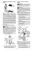
ASSEMBLY
CARTON CONTENTS
Check carton contents ag ainst the following
list:
S Brushcutter
S Cupped washer
S Large nut for installing blades
S Hex wrench
S Handlebar
S Bracket cover
S Bracket cover screws (2)
S Metal blade shield
S Blade shield screws (4)
S 4--point weed blade
S Plastic shield
S Wing nut (screwed onto plastic shield)
S Shoulder strap with warning
S Container of oil
WARNING: Alwaysstopunit anddis-
connectspark plugbeforeperforminganyas-
sembly procedures.
WARNING: If received assembled,
repeatall steps toensure your unitis properly
assembled and all fasteners are secure.
Examine parts for dam age. Do not use dam-
aged parts.
NOTE: If you need assistance or find parts
missing or damaged, call 1-800-554-6723.
It is normal for the fuel filter to rattle in the
empty fuel tank.
Finding fuelor oil residue onmuffler isnormal
due to carburetor adjustments and testing
done by the manufacturer.
TOOLS REQUIRED
S Hex wrench (provided)
S Adjustable wrench
S Phillips screwdriver
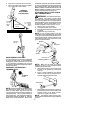
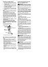
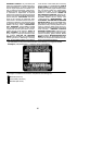
ATTACH ING THE HANDLEBAR
DANGER: To avoid serious injury , the
barrier portion ofthe handlebarmust beinstalled
as shown to provide a barrier between operator
and the spinning blade.
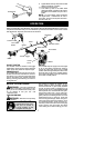
1. Locate the decal on the handlebar. This
decal includes an arrow. Position the
handlebar with the mounting bracket at
the end of the arrow.
2. Position the bracket cover over the han-
dlebar. Again make sure thehandlebar is
at the end of the arrow.
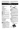
3. Insert screws an d hand tighten only. Be
sure the handlebar is installed correctly;
then, tighten each screw securely with
the hex wrench.
Screw
Mounting
Bracket
Handlebar
Bracket Cover
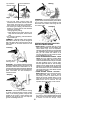
ASSEMBLY OF SHOULDER STRAP
WARNING: Proper shoulder strap
and handlebar adjustments must be made
with the engine completely stopped before
using unit.
1. Insert your right arm and head through
the shoulder strap and allow it to rest on
your left shoulder. Make sure the danger
sign isonyourback andthehookis tothe
right side of your waist.
NOTE: A one-half twist i s built in the shoul-
der strap to allow the strap to rest flat on the
shoulder.
2. Adjust the strap, allowing the hook to be
about 6 inches (15 cm) below the waist.
3. Fasten the strap hoo k to th e clamp located
between the trigger handle and the handle-
bar clamp base and lift the tool to the oper-
ating position.
4. Try on shoulder strap and adjust for fit
and b alance beforestarting theengine or
beginning a cutting operation .
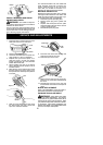
NOTE: It m ay be necessary to relocate the
shoulder strap clamp on the shaft for proper
balancing of unit.
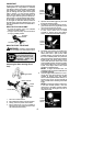
TO RELOCATE SHOULDER STRAP
CLAMP:
1. Loosen and remove both clamp screws.
2. Place the upper shoulder strap clamp
over the shaft.
3. Position the lower shoulder strap clamp
under the shaft and align the upper and
lower clamp screw holes.
Upper Shoulder
Strap Clamp
Screws
Lower Shoulder
Strap Clamp