


5
3
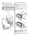
MOUNTING COVER ASSEMBLY TO
SUPPORT ASSEMBLY (See Fig. 3)
NOTE: For ease of assembly, you may wish to obtain the
as sis tance of another person for mounting coverassembly
to tractor.
1. Position cover assembly on ground behind tractor as
shown.
2. Lift and rotate cover to align cover brackets with support
assembly tubes.
3. Slide cover assembly down onto the support tubes.
FIG. 3
02532
COVER
ASSEMBLY
SUPPORT
ASSEMBLY
ASSEMBLY
0254
3
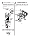
HANG SUPPORT ASSEMBLY ON
REAR DRAWBAR (See Fig. 2)
1. Slide fl anges of support assembly into drawbar slots
fi rst, then, pivot backwards inserting pin into drawbar
pin hole.
2. Be sure support assembly is seated properly, then
secure with retainer spring.
2
FIG. 2
INSERT
FLANGES
FIRST INTO
DRAWBAR
SLOTS
SUPPORT
ASSEMBLY
DRAWBAR SLOTS
RETAINER
SPRING
PIN
02051
0
2
051
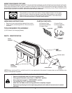
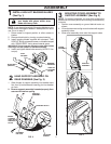
INSTALL HIGH LIFT BAGGING BLADES
(See Fig. 1)
CAUTION: Blades are sharp. Protect
your hands with gloves and/or wrap
blade with heavy cloth.
NOTE: If you already have high lift bagging blades on your
mower, store the supplied blades in a safe place for future
use. Go on to step 2.
1. Raise mower to highest position to allow access to
blades.
2. Remove blade bolts by turning counterclockwise.
3. Install bagging blades supplied with stamped "THIS
SIDE UP" facing up towards mower, or, blades stamped
with "GRASS SIDE" facing down towards grass.
IMPORTANT: To ensure proper assembly, center hole in blade
must align with star pattern on mandrel assembly.
4. Install and tighten blade bolts securely (45-55 Ft. Lbs.
torque).
02544
HIGH LIFT
BAGGING
BLADE
BLADE BOLT
(SPECIAL)
MANDREL
ASSEMBLY
FIG. 1
STAR
PATTERN
1
02051
DRAWBAR
PIN HOLE