


7
02091
02085
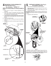
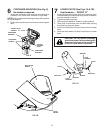
SUPPORT POST (See Fig. 3)
Use Hardware - - GROUP "B"
CAUTION: Container support is spring
loaded and locked to the cover. Handle
cover assembly carefully so as not to
unlatch the cover from the container
support.
1. Rotate cover assembly onto its side as shown.
2. Assemble support post to container support with
the three (3) carriage bolts and locknuts. Tighten
securely.
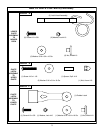
ALIGNMENT
MARKS
COVER SEAL
FIG. 2
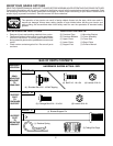
COVER SEAL (See Fig. 2)
No hardware required
1. Align mark on seal with mark at cover opening.
2. Work seal into opening so cover sits between fl anges
of seal.
2
3
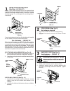
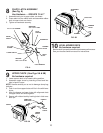
REAR MOUNTING BRACKET
(See Figs. 1A, 1B & 1C)
NOTE: If your tractor already has four (4) shoulder bolts
installed on the rear draw bar, simply hang the mounting
bracket, lanced tabs towards bottom, on the bolts. Discard
hardware group "A" and disregard the remaining Step 1
instructions.
1
If your tractor does not have four (4) shoulder bolts installed
on the drawbar, follow the instructions below.
Use Hardware - - GROUP "A"
Only one set of hardware in GROUP "A" will be used to
mount the rear mounting bracket. To determine which set
is correct for your tractor, check to see if there are (2) two
upper corner ribs on each side of drawbar. If your tractor
has the upper corner ribs, use the (4) four self tapping
shoulder bolts. If your tractor does not have the corner ribs,
use the set of (4) four bolts and locknuts.
SELF TAPPING SHOULDER BOLTS (See Fig. 1B)
1. Using the four formed holes in the drawbar, install the
four shoulder bolts as shown and tighten securely.
2. Hang the mounting bracket, lanced tabs towards bottom,
on the bolts.
LOCKNUTS
CARRIAGE
BOLTS
SUPPORT
POST
FIG. 3
LANCED TABS
TOWARD BOTTOM
0
2
3
3
7
SHOULDER
BOLTS
FIG. 1A
02
3
3
6
UPPER CORNER
RIBS
UPPER CORNER
RIBS
SELF
TAPPING
SHOULDER
BOLTS
FIG. 1B
LANCED TABS
TOWARD BOTTOM
BOLTS AND LOCKNUTS (See Fig. 1C)
1. Assemble the mounting bracket, lanced tabs towards
bottom, using the four smaller inside holes on the
drawbar.
2. Install the four bolts and locknuts as shown and tighten
securely.
02335
FIG. 1C
LANCED TABS
TOWARD BOTTOM
LOCKNUTS
BOLTS