


5
STANDARDS:
This edger attachmentis Listed by U nderwriter’s Laboratories,Inc., in ac-
cordance with UL Standard 1602, “Gasoline--Engine--Powered, Rigid--Cutting--Member,
Edgers and Edger Trimmers,” only when used with the following models:
31cc Powerhead (with trimmer attachment) PP036............................
31cc Powerhead (with trimmer attachment) PP136............................
ASSEMBLY
W ARNING:
If received assembled,
repeatall stepsto ensureyour unit i s p roperly
assembled and all fasteners are secure.
Examine parts for damage. Do not use dam-
aged parts.
NOTE:
If you need assistance or find parts
missing or damaged, call 1-800-554-6723.
TOOLS REQUIRED
S
Hex wrench (provided)
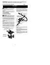
HANDLEBAR ASSEMBLY
DANGER:
RISK OF CUT. To avoid
serious injury , the barrier portion of the han-
dlebar must be installed as shown on the up-
pershaftofthepowerheadtoprovideabarrier
betweenoperatorandthe spinning blade. At-
tachshaft clampabovearrowonsafetywarn-
ing decal on the upper shaft (powerheadend
of unit). Ensure handlebar is positioned on
handlebar clamp between the arrows on the
handlebar decal.
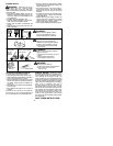
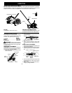
NOTE:
The shaft clamp base has four
spacer tabs attached. These tabs are pro-
vided to adapt this attachment for u se with
powerheads that have a 1
"
diameter upper
shaft(theshaftclampwill nottightendownse-
curely on the1
"
diameter upper shaft without
using these spacer tabs). The tabs must be
broken off completely before use and placed
over the screw holes on the clamp base.
These tabs are not needed for powerheads
with a 7/8
"
upper shaft.
Spacer Tabs
HANDLEBAR CLAMP BASE
Spacer Tabs
positioned for use
on 1
"
diameter
upper shaft
1. Place t heshaft c lamp overthe uppershaft
above the arrow on the safety decal.
2. Position the clamp base under the upper
shaft and align the shaft clamp and clamp
base screw holes (use spacer tabs be-
tween shaft clamp and clamp base if nec-
essary to secure clamp, i.e. for 1
"
diame-
ter upper shaft).
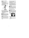
POWERHEAD
END
ATTACHMENT
END
Screws
Clamp
Base
Handlebar Clamp
between arrows on
handlebar decal
Clamp
Knob
Shaft
Clamp
Handlebar
Arrow on
Safety Decal
3. Insert the four screws into the screw
holes.
4. Secure shaft clamp by tightening screws
with the hex wrench.
5. Position the handlebar as shown, ensur-
ing t hehandlebaris positionedon thehan-
dlebar clamp between the arrows on the
handlebar decal.
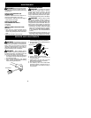
6. Retighten handlebar by turning clamp
knob clockwise until handlebar is secure
and stationary in clamp (clamp knob can-
not be overtightened).