


10
If the unit still doesn’t start, refer to
TROUBLESHOOTING TABLE or call
1-800-554-6723.
OPERATING THE COUPLER
This m odel is equipped with a coupler which
enables optional attachments to be installed.
The optional attachments are:
MODEL:
Edger PP1000E.......................
Cultivator PP2000T....................
Blower PP3000B......................
Brushcutter PP4000C..................
Pruner PP5000P......................
WARNING:
Always stop unit and dis-
connect spark plug before removing or i nstal-
ling attachments.
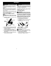
REMOVING TRIMMER ATTACH-
MENT (OR OTHER OPTIONAL AT-
TACHMENTS)
CAUTION:
When removing or ins t alling at-
tachments, place the unit on a flat surface for
stability.
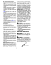
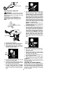
1. Loosen the coupler by turning the knob
counterclockwise.
Coupler
Knob
LOOSEN
TIGHTEN
Upper Tube
Lower
Attachment
2. Press and hold the locking/release button.
Locking/Release
Button
Coupler
Upper Tube
Lower Attachment
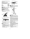
3. While securely holding the engine and
upper tube, pull the at tachment straight
out of the coupler.
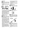
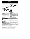
INSTALLING OPTIONAL ATTACH-
MENTS
1. Remove the tube cap from the attach-
ment (i f present).
2. Position locking/release button of attach-
ment into guide recess of coupler.
3. Push the attachment into the coupler until
the locking/release button snaps into the
primary hole.
4. Before using the unit, tighten the knob se-
curely by turning clockwise.
Coupler
Primary Hole
Upper
Tube
Locking/
Release
Button
Attachment
Guide Recess
WARNING:
Make sure the locking/
release button is locked i n the primary hole
and the knob is securely tightened before op-
erating the unit.
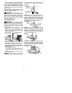
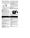
OPERATING POSITION
Cut from your left to your right.
WARNING:
Always weareyeprotec-
tion. Never lean over the trimmer head.
Rocks ordebris canricochet orbe throwninto
eyes and face and cause blindness or other
serious injury.
Do not run the engine at a higher speed than
necessary. The cutting line will cut efficiently
whenthe engine isrunat less t han fullthrottle.
At lower speeds, there is less engine noise
and vibration. The cutting line w ill last longer
and will be less likely to “weld” ont o the spool.
Always release the thr ottle trigger and allow the
engine to return to idle speed when not cutting.
To stop engine:
S
Release the throttle trigger.
S
Move the ON/OFF switch to the O FF posi-
tion.
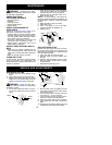
TRIMMER LINE ADVANCE
Thetrimmer line will adv ance approximately 2
in. (5 cm) each time the bottom of the trimmer
head is tapped on the ground with the engine
running at full throttle.
The most efficient line length is the maximum
length allowed by the line limiter.
Always keep the shield in place when the tool
is being operated.
To advance line:
S
Operate the engine at full throttle.
S
Hold the trimmer head paral lel to andabove
the grassy area.