


3
CUTTING SAFETY
WARNING:
Inspect the area before
each use. Remove objects (rocks, broken
glass, nails, wire, etc.) which can be thrown
by or become entangled in line. Hard objects
can damage the trimmer head and be thrown
causing serious injury.
S
Use only for trimm ing, scalping, mowing and
sweeping. Do not use for edging, pr uning or
hedge trimming.
S
Keep fir m footing and balance. D o not over-
reach.
S
Keep all parts ofyour bodyaway frommuffler
and spinning line. Keep engine bel ow waist
level. A hot muffler can cause serious burns.
S
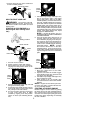
Cut from your left to your right. C utting on
right side of the shield will throw debris away
from the oper ator.
S
Use only in daylight or good artificial light.
S
Use only for jobs explained in this manual.
TRANSPORTING AND STORAGE
S
Allow engine tocool before storing ortrans-
porting in vehicle.
S
Empty the fuel tank before storing or trans-
porting the unit. Useupfuel left inthecarbu-
retor by starting the engine and letting it run
until it stops.
S
Store unitand fuelin areawhere fuelvapors
cannot reach sparks or open flames from
water heaters, electric motors or switches,
furnaces, etc.
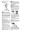
S
Store unit so line limiter blade cannot acci-
dentally cause injury. The unit can be hung
by the tube.
S
Store unit out of reach of children.
SAFETY NOTICE:
Exposure to vibrations
through prolonged use of gasoline powered
hand tools could cause blood vessel ornerve
damage in the fingers, hands, and joints of
people prone to circulation disorders or ab-
normal swellings. Prolonged use in cold
weather hasbeen linked toblood vessel dam-
age inotherwise healthy people. Ifsymptoms
occur such as numbness, pain, l oss of
strength, change in skin color or texture, or
loss of feeling in the fingers, hands, or joints,
discontinue the use ofthis tool and seekmed-
ical attention. An anti --vibration system does
not guarantee the a voidance of these prob-
lems. Users who operate power tools on a
continual and regular basis must monitor
closely their physical condition and the condi-
tion of this tool.
SPECIAL NOTICE:
This unit is equipped
with a temperature limiting muffler and spark
arresting screen which meets the require-
ments of California Codes 4442 and4443. All
U.S. forest land and the states of C alifornia,
Idaho, Maine, Minnesota, New Jersey, Ore-
gon, and Washington require by law that
many internal combustion engines be
equipped withasparkarresting screen. Ifyou
operate inalocale wheresuch regulations ex-
ist, you arelegally responsible formaintaining
the operating condition of these parts. Failure
to do so is a violation of the law. For normal
homeowner use,the mufflerand sparkarrest-
ing screen will not require any service. After
50 hours of use, we recommend that your
muffler be serviced or replaced by an autho-
rized service dealer.
ASSEMBLY
WARNING:
If received assembled,
repeat all steps to ensure your unit is properly
assembled and all fasteners are secure.
Examine parts for damage. Do not use dam-
aged parts.
NOTE:
If you need assistance or find parts
missing or damaged, call 1-800-554-6723.
It is norm al for the fuel filter to rattle in the
empty fuel tank.
Finding fuel or oil residue on muffler is norm al
due to carburetor adjustments and testing
done by the manufacturer.
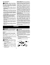
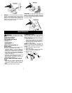
ADJUSTING THE HANDLE
WARNING:
When adjusting the han-
dle, be sure it remains between the trigger
and the safety decal.
1. Loosen handle by turning T--handle/
screw counterclockwise.
2. Rotate the handle on the tube to an upr ight
position.
3. Adjust handle to a comfortable position
between the trigger and the safety label
on the tube.
4. Retighten handle by turning T--handle/
screw clockwise.
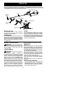
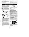
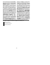
ATTACHING SHIELD
WARNING:
The shield must be prop-
erly installed. The s hieldprovides partial pr otec-
tion to the oper ator and others fr om the risk of
thrown objects, and is equipped witha line limit-
er blade which c uts excess line to the proper
length. The line limiter blade (on under side of
shield) is shar p and can cut you.
For proper orientation of shield, see KNOW
YOUR TRIM M ER illustr a tio n in OPER ATION
section.
1. Remove wing nut from shield.
2. Insert bracket into slot as shown.
3. Pivot shield until bolt passes through hole
in bracket.
4. Securely tighten wing nut onto bolt.
Wing Nut
Bracket
Slot
Shield
Gearbox