


12
OPERATION
TO OPERATE ON HILLS
WARNING: Do not drive up or down
hills with slopes greater than 15° and
do not drive across any slope.
• Choose the slowest speed before starting up or down
hills.
• Avoid stopping or changing speed on hills.
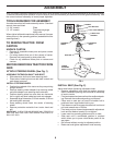
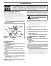
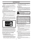
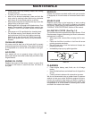
AT TACH MENT
CLUTCH LEVER
"DISENGAGED" PO-
SI TION
ATTACHMENT
LIFT LEVER
HIGH PO SI TION
"ENGAGED" PO SI TION
LOW
POSITION
DEFLECTOR
SHIELD
FIG. 7
TO OPERATE MOWER (See Fig. 7)
Your tractor is equipped with an operator presence sensing
switch. Any attempt by the operator to leave the seat with
the engine running and the attachment clutch engaged
will shut off the engine. You must remain fully and centrally
positioned in the seat to prevent the engine from hesitating
or cutting off when operating your equipment on rough,
rolling terrain or hills.
• Select desired height of cut.
• Start mower blades by engaging attachment clutch
control.
• TO STOP MOWER BLADES - disengage attachment
clutch con trol.
CAUTION: Do not operate the mower
without either the en tire grass catcher,
on mowers so equipped, or the defl ector
shield in place.
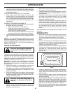
REVERSE OPERATION SYSTEM (ROS)
Your tractor is equipped with a Reverse Operation System
(ROS). Any attempt by the operator to travel in the reverse
direction with the attachment clutch engaged will shut off
the engine unless ignition key is placed in the ROS "ON"
position.
WARNING: Backing up with the attachment clutch en-
gaged while mowing is strongly discouraged. Turning the
ROS "ON", to allow reverse operation with the attachment
clutch engaged, should only be done when the operator
decides it is necessary to reposition the machine with the
attachment engaged. Do not mow in reverse unless
absolutely necessary.
USING THE REVERSE OPERATION SYSTEM -
• Move motion control lever to neutral (N) position.
• With engine running, turn ignition key counterclockwise
to ROS "ON" position.
• Look down and behind before and while backing.
• Slowly move motion control lever to reverse (R) po si tion
to start movement.
• When use of the ROS is no longer needed, turn the
ignition key clockwise to engine "ON" position.
0
2
8
2
8
ROS "ON" POSITION
ENGINE "ON" POSITION
(NORMAL OPERATING)
014
2
3
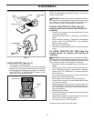
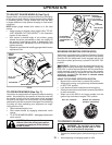
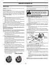
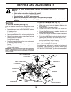
TO ADJUST GAUGE WHEELS (See Fig. 6)
Gauge wheels are properly adjusted when they are slightly
off the ground when mower is at the desired cutting height
in operating position. Gauge wheels then keep the deck
in proper position to help prevent scalping in most terrain
conditions.
NOTE:Adjust gauge wheels with tractor on a fl at level
surface.
• Adjust mower to desired cutting height (See “TO AD-
JUST MOWER CUT TING HEIGHT” in the Operation
sec tion of this manual).
• With mower in desired height of cut po si tion, gauge
wheels should be assembled so they are slightly off
the ground. In stall gauge wheel in appropriate hole
with shoulder bolt, 3/8 washer, and 3/8-16 locknut and
tighten se cure ly.
• Repeat for opposite side installing gauge wheel in same
adjustment hole.
3/8 WASH ER
3/8-16
LOCKNUT
GAUGE
WHEEL
MOUNTING
BRACKET
SHOULDER
BOLT
GAUGE WHEEL
FIG. 6