


19
SERVICE AND ADJUSTMENTS
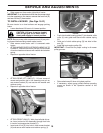
• Slide mower out from under right side of tractor.
IMPORTANT: If an attachment other than the mower deck
is to be mounted on the trac tor, remove the front link (E)
and rear lift liks (C) from tractor.
A
B
C
D
FIG. 18
FIG. 19
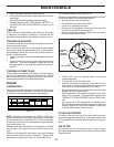
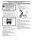
TO INSTALL MOWER (See Figs. 18-21)
Be sure tractor is on level surface and engage park ing
brake.
• Lower attachment lift lever to it's lowest position.
CAUTION: Lift lever is spring loaded.
Have a tight grip on lift lever, lower it
slowly and engage in lowest position.
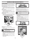
NOTE: Be sure mower side suspension arms (A) are point-
ing forward before sliding mower under tractor.
• Slide mower under tractor until it is centered under
tractor.
• ATTACH MOWER SIDE SUSPENSION ARMS (A) TO
CHASSIS - Position hole in arm over pin (B) on outside
of tractor chassis and secure with washer and retainer
spring.
• Repeat on opposite side of tractor.
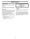
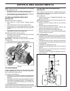
• ATTACH REAR LIFT LINKS (C) - Lift rear corner of
mower and position slot in link assembly over pin on
rear mower bracket (D) and secure with washer and
retainer spring.
• Repeat on opposite side of tractor.
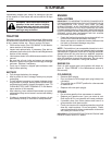
• ATTACH FRONT LINK (E) - Work from left side of trac-
tor. Insert rod end of link assembly through front hole
in tractor front suspension bracket (F).
• Insert end of link (E) into hole in front mower bracket
(H) and secure with washer and retainer spring (J).
E
F
H
J
M
FIG. 20
FIG. 21
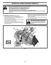
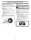
• Push clutch cable housing guide (P) into bracket, slide
collar (L) onto guide and secure with retainer spring
(K).
• Hook end of clutch cable spring (Q) into hole in idler
arm (R).
• Install belt onto engine pulley (M).
IMPORTANT: Check belt for proper routing in all mower
pulley grooves.
• Raise attachment lift lever to highest position.
• If necessary, adjust gauge wheels before op er at ing
mower as shown in the Operation section of this
manual.