


8
ASSEMBLY
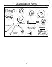
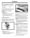
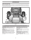
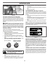
• ATTACH REAR LIFT LINKS (C) - Insert rod end of lift
link assembly into hole in tractor lift shaft suspension
arm (L) and pivot link down to mower. Lift rear corner
of mower and position slot in link assembly over pin on
rear mower bracket (D) and secure with washer and
retainer spring.
• Repeat on opposite side of tractor.
• ATTACH MOWER SIDE SUSPENSION ARMS (A) TO
CHASSIS - Position hole in arm over pin (B) on outside
of tractor chassis and secure with washer and retainer
spring.
• Repeat on opposite side of tractor.
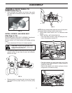
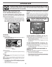
• Turn steering wheel to position wheels straight for-
ward.
• ATTACH FRONT LINK (E) - Work from left side of
tractor. Insert rod end of link assembly through front
hole in tractor front suspension bracket (F) and secure
with7/16 retainer spring (G) through hole in link located
behind the bracket.
• Insert other end of link (E) into hole in front mower
bracket (H) and secure with washer and 5/16 retainer
spring (J).
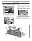
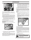
• Disengage belt tension rod (K) from locking bracket
(L).
• Install belt onto engine clutch pulley (M).
IMPORTANT: Check belt for proper routing in all mower
pulley grooves.
A
B
D
C
B
H
E
F
M
L
A
K
S
FIG. 8
FIG. 9
FIG. 10
FIG. 11
E
F
H
G
J
5/16
7/16
C
D
L