


5
ASSEMBLY
02530
0
253
1
1
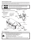
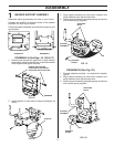
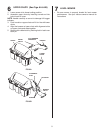
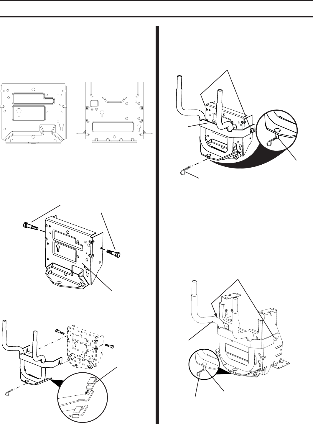
DRAWBAR A (See Figs. 1A, 1B & 1C)
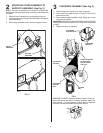
1. Remove and discard the upper bolt on both sides of
the drawbar. Using the same holes, install the shoulder
bolts supplied and tighten securely.
DRAWBAR
SHOULDER
BOLTS
SUPPORT
ASSEMBLY
RETAINER
SPRING
PIN
FIG. 1A
REMOVE AND DISCARD
UPPER BOLTS AND INSTALL
SHOULDER BOLTS SUPPLIED
FIG. 1C
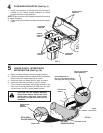
2. Install adapter to both sides of support assembly as
shown.
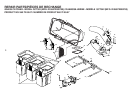
BAGGER SUPPORT ASSEMBLY
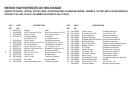
Determine which type drawbar you have on your tractor.
Compare the drawbar illustrations below to the drawbar
located at the rear of your tractor.
Follow the support assembly instructions that apply to your
type drawbar.
DRAWBAR A
DRAWBAR B
3. Align support assembly pin with hole in drawbar and
hang assembly over the shoulder bolts.
4. Be sure support assembly is seated properly and secure
with retainer spring supplied.
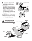
DRAWBAR B (See Fig. 1D)
1. Discard adapters provided - not required for drawbar
type B.
2. Align support assembly pin with hole in drawbar and
hang assembly over the shoulder bolts.
3. Be sure support assembly is seated properly and secure
with retainer spring supplied.
3064
SHOULDER
BOLTS
SUPPORT
ASSEMBLY
RETAINER
SPRING
PIN
FIG. 1D
FIG. 1B
ADAPTER