


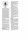
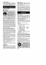
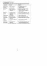

Computed kickback angle (CKA
BAR
MODEL
1950/1975/
2050/2050WT
2055/2075/
2150/215OPR
2155/2175/
2350/2375
Table
P/N Length CHAIN P/N
952044368 14" 952051209
952044370 16" 952051211
952044418 18" 952051338
CKA without chain brake
24
19'
14
NOTE: If this saw is to be used for com-
mercial logging, a chain brake is required
and shatl not be removed or otherwise dis-
ab+ed to comply with Federal OBHA Regula-
tions for Commercial Logging.
_kWARNING: The engine exhaust
from this product contains chemicals known
to the State of California to cause cancer,
birth defects or other reproductive harm.
SAFETY NOTICE: Exposure to vibrations
through prolonged use of gasoline powered
hand tools couid cause blood vesse_ or nerve
damage in the fingers, hands, and joints of
beagle prone to circulation disorders or
abnormal swe}lings. Prolonged use in cold
weather has been tinked to blood vessel
damage in otherwise healthy people. If
symptoms occur such as numbness, pain,
loss of strength, change in skin color or texture,
or loss of feeling inthe fingers, hands, or joints,
disconbnue the use of this too+ and seek
medicat attention. An anti-vibration system
does not guarantee the avoidance of these
problems. Users who operate power toots on
a continua+ and regular basis must monitor
closely their physical cond+tion and the
cond_on of this tool
SPECIAL NOTICE: Your saw is equipped
with a temperature liming muffler and spark
arresbng screen which meets the
requirements of California Codes 4442 and
4443. All U.S. forest land and the states of
California+ Idaho, Maine, Minnesota, New
Jersey, Oregon, and Washington require by
faw that many internal combustion engines to
be equipped with a spark arresting screen if
you operate a chain saw in a state or locale
where such regulations exist, you are legally
responsibte for maintaining the operating
cond_on of these parts. Failure to do so is a
victet_on of the law. Refer to the SERVICE
section for maintenance of the spark arresting
screen. Fd+iure to follow all Safety Rules and
Precautions can result in serious injury. If
situations occur which are not covered in this
manual, use care and good judgement, ff you
need assistance, contact your authorized
service dealer or cali t-800-554-6723.
Protective gloves (not provided) should be
worn during assembly
ATTACHING TH E BAR &CHAIN (If not
already attached)
WARNING: if received assembled,
repeat all steps to ensure your saw is properly
assembled and all fasteners are secure. Al-
ways wear gloves when handling the chain.
The chain is sharp and can cut you even when
is not moving!
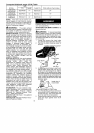
1. Loosen and remove the chain brake
nuts and the chain brake from the saw.
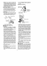
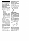
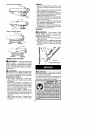
2 Remove the pIastic shipping spacer (if
present).
Location of shipping spacer
a_ Chain Brake
Ch Nuts
Bar Tool
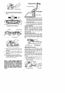
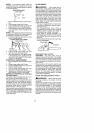
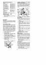
3. An adjusting pin and screw Lsused to ad-
just the tens+on of the cha+n It is very im-
portant when assembling the bar, that the
pin facated on the adjusting screw aligns
into a hole in the bar. Turning the screw will
move the adjustment pin up and down the
screw. Locate this adjustment before you
begin mounting the bar onto the saw. See
il:ustrationbelow.
STANDARDS: This saw is listed by Under-
writer's Laboratories, inc., in accordance with:
ANSi B175.1-2000 American National
Standards for Gasoline-Powered Chain
Saws - Safety Requirements
CSA Z62.1-03 Chain Saws - Occupabenal
Health and Safety
CSA Z62.g-96 Chain Saw Kickback Occu-
pational Health and Safety
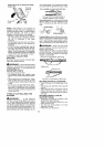
Adjustment facated on Chain Brake
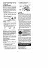
4. Turn the adjusting screw by hand coun-
terclockwise untii the adjusting pin just
touches the stop. This should allow the
pin to be near the correct position.
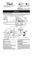
5 Slide guide bar behind c+utoh drum until
guide bar stops against crutch drum
sprocket.