


6
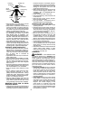
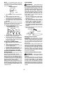
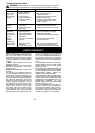
Computed kickback angle (CKA) Table
BAR
P/N Length CHAIN P/N
952044368 14″
MODEL
CKA without chain brake
1950/1975/
2050/2050WT
24_
2055/2075/
2150/2150PR
2155/2175/
2350/2375
16″
18″ 14_
952051209
952051211
952051338
952044370
952044418
19_
NOTE: Ifthissawistobeusedforcom-
mercial logging, a chain brake is required
and shall not be removed or otherwise dis-
abled to com ply with Federal OSHA Regula-
tions for Comm ercial Logging.
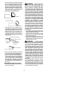
SAFETY NOTICE: Exposure to vibrations
through prolonged use of gasoline powered
hand tools could cause blood vessel or nerve
damage in the fingers, hands, and joints of
people p rone to c irculation disorders or
abnormal swellings. Prolonged use in cold
weather has been linked to blood vessel
damage in otherwise healthy people. If
symptoms occur such as numbness, pain,
loss of strength, change in skin color or texture,
or loss of feeling in the fingers, hands, or joints,
discontinue the use of this tool and seek
medical attention. An anti-vibration system
does not guarantee the avoidance of these
problems. Users who operate power tools on
a continual and regular basis must monitor
closely their physical condition and the
condition of this tool.
SPECIAL NOTICE:Yoursaw i sequipped
with a temperature limiting muf fler and s park
arresting screen which meets the
requirements of California Codes 4442 and
4443. All U.S. forest land and the states of
California, Idaho, Maine, Minnesota, New
Jersey, Oregon, and Washington require by
law that many internal combustion engines
tobe equipped with aspark arrestingscreen.
If you oper atea chain saw ina state or locale
where suchregulations exist, you are legally
responsible for maintaining the operating
condition of these parts. Failure to do so i s
a violation of the law. Refer to the SERVICE
section for m aintenance of the spark
arresting screen.
Failure to follow allSafety Rules andPrecau-
tions can result in serious injury. If situations
occur which a re not covered in this manual,
use care and good judgement. If you need
assistance, contact your authorized service
dealer or call 1- 800--554--6723.
STAN DARD S: This saw is listed b y Unde r-
writer’s Laboratories, Inc., in accordance with:
ANSI B175.1--2000 American National
Standards for Gasoline--Powered Chain
Saws -- Safety Requirements
CSA Z62.1--03 Chain Saws -- Occupational
Health and Safety
CSA Z62.3--96 Chain Saw Kickback Occu-
pational Health and Safety
ASSEMBLY
Protective gloves (not provided) should be
worn during assembly.
ATTACHING THE BAR &CHAIN (If not
already attached)
WARNING: If received assembled,
repeat all steps to ensure your saw is properly
assembled and all fasteners are secure. Al-
ways wear gloves when handling the chain.
The chain is sharp and can cut you even when
it is not m oving!
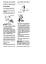
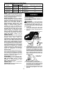
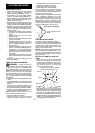
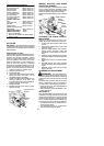
1. Loosen and remove the chain brake
nuts and the chain brake from the saw.
2. Remove the plastic shipping spacer (if
present).
Chain Brake
Chain Brake
Nuts
Bar Tool
Location o
f
shipping spacer
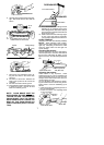
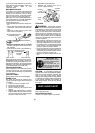
3. An adjusting pin and screw is used to a d-
just the t ension of t he cha in. It is very im -
portant when assembling the bar , t hat the
pin located on the adjusting screw aligns
into a h ol e in t hebar . T urni ng t he screw w ill
move the adjustment pin up and do wn the
screw. Locate this adjustment before you
begin mounting the ba r onto the saw . See
illustration below.
Adjustment located on Chain Brake
Inside view of
Chain Brake
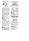
4. Turn the adjusting screw by hand coun-
terclockwise until the adjusting pin just
touches the stop. This should allow the
pin to be near the correct position.
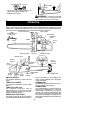
5. Slide guide bar behind clutch drum until
guide bar stops against clutch drum
sprocket.