


7
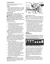
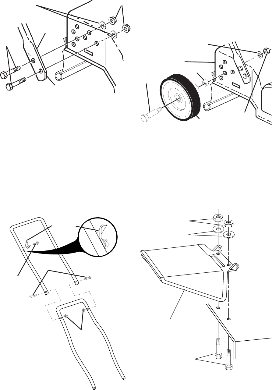
Locknuts
Hex
bolts
Cut-off fl at forward
Flat washers
Lower
handle
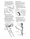
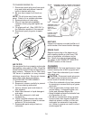
ASSEMBLE UPPER HANDLE
1. Position upper handle over lower
handle with small hole for mounting
up-stop bracket to right side and as-
semble 1/4-20 x 1-1/2 hex bolts and
1/4-20 lock nuts. Tighten se curely.
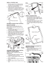
ASSEMBLE UPSTOP BRACKET
2. Position upstop bracket on the right
inside of upper handle as shown.
3. Install the hex washer head screw into
the hole in up-stop bracket and upper
handle. Tighten securely.
AS VIEWED FROM FRONT OF MOWER
Up-stop
bracket
Hex
washer
head
screw
Lock
nuts
Hex
bolts
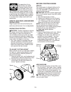
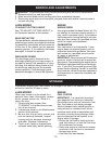
ASSEMBLE WHEELS
Cutting height is determined by as sem -
bling the wheels in one of four possible
positions on the mower hous ing. All
wheels must be in the same height posi-
tion for even cutting.
1. For each wheel, assemble shoul der
bolt and spacer as shown.
2. Assemble 1-1/4" diameter washers
(rear wheels only) and 3/8-16 lock nuts
on inside of mower housing and tighten
securely.
Spacer
Wheel
3/8-16
Locknut
1-1/4" diameter Washer
(Rear wheels only)
Mower housing
Shoulder
bolt
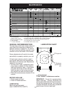
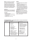
ASSEMBLE DIS CHARGE GUARD
1. Place discharge guard on top of lawn
mower dis charge opening.
2. Install two (2) 1/4-20 x 3/4 hex bolts
through hous ing and discharge guard.
3. Install two (2) 3/4" diameter wash ers
and two (2) 1/4-20 lock nuts. Tighten
se cure ly.
Locknuts
Washers
Discharge guard
Hex bolts
1. Position lower handle on housing so
cut-off fl at is forward as shown.
2. Align holes in handle with holes in
housing as shown and as sem ble 3/8-
16 x 3/4 hex bolts, fl at wash ers, and
locknuts. Tight en se cure ly.
3. Repeat for opposite side of mower.