


22
SERVICE AND ADJUSTMENTS
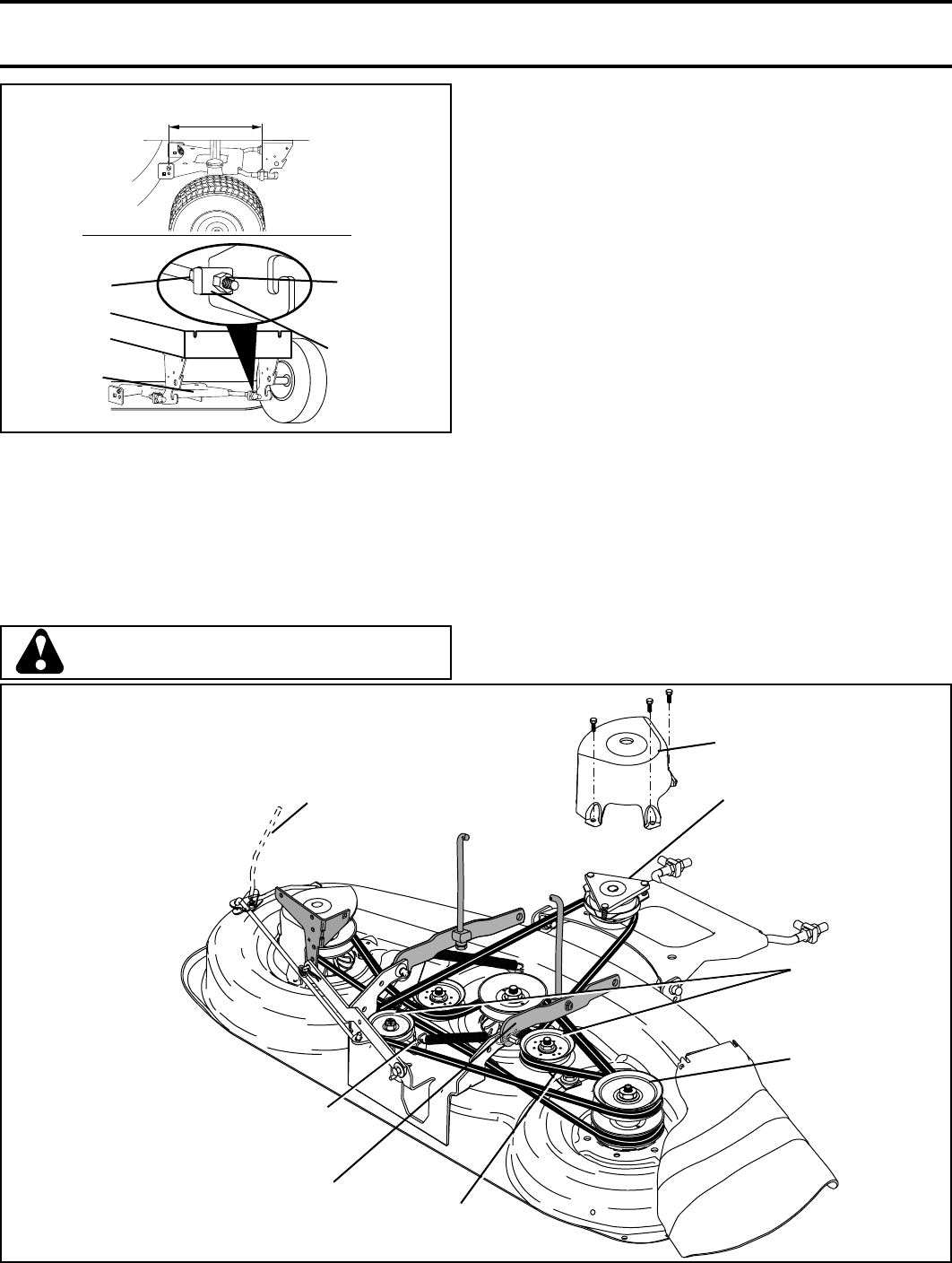
02517
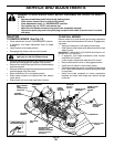
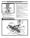
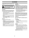
BOTH FRONT PLATE LINKS MUST BE
EQUAL IN LENGTH
TRUN NION
FRONT PLATE AS-
SEM BLY
NUT “C”
NUT “D”
FIG. 22
02516
02513
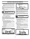
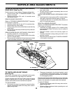
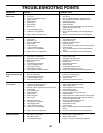
FIG. 23
PRI MA RY
IDLER ARM
R.H.
MANDREL
IDLER
PUL LEYS
ELEC TRIC
CLUTCH
PUL LEY
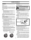
TO REPLACE MOWER DRIVE BELT
MOWER DRIVE BELT REMOVAL (See Fig. 23)
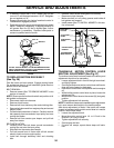
• Park tractor on a level surface. En gage parking
brake.
• Lower mower to its lowest position.
• Disengage belt tention rod from lock bracket.
CAUTION: Rod is spring loaded. Have a
tight grip on rod and release slowly.
SPRING
ARM
BELT TENSION
ROD(DISENGAGED
POSITION)
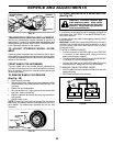
RH MAN DREL
COVER
• Remove screws from R.H. mandrel cover and remove
cover.
• Remove any dirt or grass clippings which may have
accumulated around mandrels and entire upper deck
surface.
• Disconnect R.H. suspension arm from rear deck bracket
by removing retainer spring.
• Roll belt over the top of R.H. mandrel pulley carefully.
• Remove belt from electric clutch pulley.
• Remove belt from idler pulleys.
• Check primary idler arm and two idlers to see that they
rotate freely.
• Be sure spring is securely hooked to primary idler arm
and spring arm.
MOWER DRIVE BELT INSTALLATION
• Install belt in both idlers.
• Install new belt onto electric clutch pulley.
• Roll belt into upper groove of R.H. mandrel pulley care-
fully.
• Carefully check belt routing making sure belt is in the
grooves correctly.
• Reconnect R.H. suspension arm to rear deck bracket
with retainer spring.
• Reassemble R.H. mandrel cover.
• Engage belt tension rod by pushing rod into locking
bracket.
RH SUS PEN SION
ARM