


21
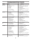
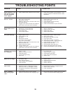
SERVICE AND ADJUSTMENTS
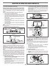
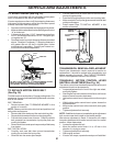
TO ADJUST BRAKE (See Fig. 23)
Your tractor is equipped with an adjustable brake system
which is mounted on the side of the transaxle.
If tractor requires more than six (6) feet stopping distance at
high speed in highest gear on a level dry concrete or paved
surface, then brake must be adjusted.
• Depress clutch/brake pedal and engage parking brake.
• Measure distance between brake operating arm and nut
“A” on brake rod.
• If distance is other than 1-9/16", loosen jam nut and turn
nut “A” until distance becomes 1-9/16". Retighten jam
nut against nut “A”.
• Road test tractor for proper stopping distance as stated
above. Readjust if necessary. If stopping distance is
still greater than six (6) feet in highest gear, further
maintenance is necessary. Contact your nearest au-
thorized service center/department.
WITH PARKING BRAKE “ENGAGED”
JAM NUT
DO NOT TOUCH THIS NUT. IF FURTHER BRAKE ADJUST-
MENT IS NECESSARY CONTACT YOUR NEAREST
AUTHORIZED SERVICE CENTER/DEPARTMENT
OPERATING
ARM
NUT
“A”
FIG. 23
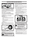
FIG. 24
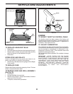
TRANSAXLE MOTION CONTROL LEVER
NEUTRAL ADJUSTMENT(See Fig. 25)
The motion control lever has been preset at the factory and
adjustment should not be necessary.
• Loosen adjustment bolt in front of the right rear wheel,
and lightly tighten.
• Start engine and move motion control lever until tractor
does not move forward or backward.
• Hold motion control lever in that position and turn engine
off.
• While holding motion control lever in place, loosen the
adjustment bolt.
• Move motion control lever to the neutral (N) (lock gate)
position.
• Tighten adjustment bolt securely.
NOTE: If additional clearance is needed to get to adjustment
bolt, move mower deck height to the lowest position.
After above adjustment is made, if the tractor still creeps
forward or backward while motion control lever is in neutral
position, follow these steps:
• Loosen the adjustment bolt.
• Move the motion control lever 1/4 to 1/2 inch in the
direction it is trying to creep.
• Tighten adjustment bolt securely.
• Start engine and test.
• If tractor still creeps, repeat above steps until satisfied.
TRANSMISSION REMOVAL/REPLACEMENT
Should your transmission require removal for service or
replacement, it should be purged after reinstallation and
before operating the tractor. See “PURGE TRANSMIS-
SION” in the Operation section of this manual.
1-9/16"
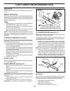
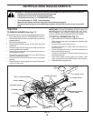
ENGINE
PULLEY
CLUTCHING
IDLER
STATIONARY
IDLER
TRANSMISSION
INPUT PULLEY
TO REPLACE MOTION DRIVE BELT
(See Fig. 24)
Park the tractor on level surface. Engage parking brake. For
assistance, there is a belt installation guide decal on bottom
side of left footrest.
BELT REMOVAL -
• Remove mower (See “TO REMOVE MOWER” in this
section of manual).
NOTE: Observe entire motion drive belt and position of all
belt guides and keepers.
• Remove belt from stationary idler and clutching idler.
• Remove belt downward from around engine pulley.
• Pull belt slack toward rear of tractor. Carefully remove
belt upwards from transmission input pulley and over
cooling fan blades.
• Remove belt from center span keeper and pull belt away
from tractor.
BELT INSTALLATION -
• Carefully work new belt down around transmission
cooling fan and onto the input pulley.
• Slide belt into the center span keeper.
• Pull belt toward front of tractor and roll around the top
groove of engine pulley.
• Install belt through stationary idler and clutching idler.
• Make sure belt is in all pulley grooves and inside all belt
guides and keepers.
• Install mower (See “TO INSTALL MOWER” in this
section of manual).