


22
SERVICE AND ADJUSTMENTS
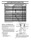
FIG. 26
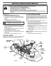
L.H.
MANDREL
CENTER MANDREL
IDLER
PULLEY
R.H. MANDREL COVER
SPRING
FIG. 25
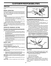
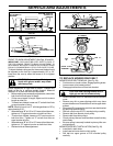
TO REPLACE MOTION DRIVE BELT
(See Fig. 27)
Park the tractor on level surface. Engage parking brake. For
assistance, there is a belt installation guide decal on bottom
side of left footrest.
• Remove mower (See “TO REMOVE MOWER” in this
section of this manual.)
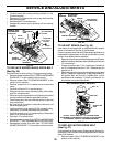
TO REPLACE MOWER BLADE DRIVE BELT
(See Fig. 25)
Park the tractor on level surface. Engage parking brake.
• Remove mower drive belt (See “TO REPLACE MOWER
DRIVE BELT” in this section of this manual).
• Remove mower (See “TO REMOVE MOWER” in this
section of this manual).
• Remove screws from L.H. mandrel cover and remove
cover.
• Carefully roll belt off L.H. mandrel pulley.
• Remove belt from center mandrel pulley, idler pulley,
and R.H. mandrel pulley.
• Remove any dirt or grass which may have accumulated
around mandrels and entire upper deck surface.
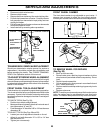
• Check secondary idler arm and idler pulley to see that
they rotate freely.
• Be sure spring is hooked in secondary idler arm and
secondary spring arm.
• Install new belt in lower groove of R.H. mandrel pulley,
idler pulley, and center mandrel pulley as shown.
• Carefully roll belt over L.H. mandrel pulley. Make sure
belt is in all grooves properly.
• Reinstall L.H. mandrel cover.
• Reinstall mower to tractor (See “INSTALL MOWER AND
DRIVE BELT” in the Assembly section of this manual).
• Reassemble mower drive belt (See “TO REPLACE
MOWER DRIVE BELT” in this section of this manual).
SECONDARY
IDLER ARM
SECONDARY
SPRING ARM
FIG. 24
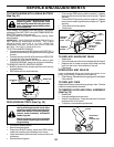
• Carefully check belt routing making sure belt is in the
grooves correctly.
• Reconnect R.H. suspension arm to rear deck bracket
with retainer spring.
• Reassemble R.H. mandrel cover.
• Engage belt tension rod by pushing rod into locking
bracket.
PRIMARY
IDLER ARM
R.H.
MANDREL
IDLER
PULLEY
ELECTRIC
CLUTCH
PULLEY
SPRING
ARM
BELT
TENSION ROD
(DISENGAGED
POSITION)
RH MANDREL
COVER
RH
SUSPENSION
ARM
IDLER
PULLEY
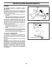
WITH PARKING BRAKE “ENGAGED”
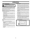
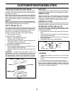
JAM NUT
DO NOT TOUCH THIS NUT. IF FURTHER BRAKE
ADJUSTMENT IS NECESSARY CONTACT YOUR NEAREST
AUTHORIZED SERVICE CENTER/DEPARTMENT
OPERATING
ARM
NUT “A”
1-3/4"
TO ADJUST BRAKE (See Fig. 26)
Your tractor is equipped with an adjustable brake system
which is mounted on the side of the transaxle.
If tractor requires more than six (6) feet stopping distance at
high speed in highest gear on a level dry concrete or paved
surface, then brake must be adjusted.
• Depress clutch/brake pedal and engage parking brake.
• Measure distance between brake operating arm and nut
“A” on brake rod.
• If distance is other than 1-3/4", loosen jam nut and turn
nut “A” until distance becomes 1-3/4". Retighten jam nut
against nut “A”.
• Road test tractor for proper stopping distance as stated
above. Readjust if necessary. If stopping distance is
still greater than six (6) feet in highest gear, further
maintenance is necessary. Contact your nearest au-
thorized service center/department.