


8
ASSEMBLY
NOSE
ROLLER
“A”
BRACKET
TAB
WASHER
TAB
HOLE
LOCK NUT
“B”
BRACKET
TAB
FIG. 5
HEX
BOLT
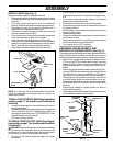
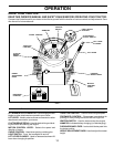
TO ATTACH NOSE ROLLER (See Fig. 5)
• Position brackets, 17/32 x 7/8 x 16 gauge washers, and
nose roller between deck mounting brackets as shown.
Be sure to position brackets on correct side, as shown.
• Install hex bolts and lock nuts as shown. Tighten
hardware securely.
NOTE: Be sure bracket tabs are positioned in tab holes in
deck brackets.
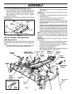
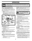
INSTALL MOWER AND DRIVE BELT
(See Figs. 6 and 7)
Be sure tractor is on level surface and mower suspension
arms are raised with attachment lift control. Engage parking
brake.
• Cut and remove ties securing anti-sway bar and belts.
Swing anti-sway bar to left side of mower deck.
FIG. 6
• Slide mower under tractor with deflector shield to right
side of tractor.
IMPORTANT: Check belt for proper routing in all mower
pulley grooves.
• If equipped, turn height adjustment knob counterclock-
wise until it stops.
• Lower mower linkage with attachment lift control.
• Install belt into electric clutch pulley groove.
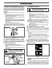
• Place the suspension arms on inward pointing deck
pins. Retain with double loop retainer spring with loops
down as shown.
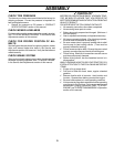
• Install front plate assembly to tractor suspension brack-
ets and retain with single loop retainer springs as shown.
• Position front plate assembly between front mower
brackets. Raise deck and plate assembly to align holes
and insert flanged pins. Secure pins with double loop
retainer springs between the plate and mower brackets.
NOTE: To assist in locating hole in flanged pin, the hole in
pin is inline with notch on head of pin. If necessary, move
mower side-to-side to give space between plate and mower
brackets.
IMPORTANT: Check belt for proper routing in all mower
pulley grooves.
• Connect anti-sway bar to chassis bracket under left
footrest and retain with double loop retainer spring.
• If equipped, turn height adjustment knob clockwise to
remove slack from mower suspension.
• Raise deck to highest position.
• Adjust gauge wheels before operating mower as shown
in the Operation section of this manual.
CHASSIS
BRACKET
ANTI-SWAY
BAR
DOUBLE
LOOP
RETAINER
SPRING
GAUGE
WHEEL
IDLER
PULLEY
SUSPENSION ARMS
FRONT
MOWER
BRACKET
DEFLECTOR
SHIELD
SINGLE LOOP
RETAINER
SPRINGS
DOUBLE LOOP
RETAINER SPRING
(Inward pointing deck pins)
ELECTRIC
CLUTCH
PULLEY
FRONT
SUSPENSION
BRACKETS
USE PLIERS FOR
RETAINER SPRINGS
LOOP
DOWN
FLANGED PIN
FRONT
PLATE
ASSEMBLY