


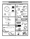
7
ASSEMBLY
TO ROLL TRACTOR OFF SKID (See Opera-
tion section for location and function of con-
trols)
• Press lift lever plunger and raise attachment lift lever to
its highest position.
• Release parking brake by depressing brake pedal.
• Place freewheel control in freewheeling position to
disengage transmission (See “TO TRANSPORT” in the
Operation section of this manual).
• Roll tractor forward off skid.
TO DRIVE TRACTOR OFF SKID (See Opera-
tion section for location and function of con-
trols)
WARNING: Before starting, read, understand and follow
all instructions in the Operation section of this manual. Be
sure tractor is in a well-ventilated area. Be sure the area in
front of tractor is clear of other people and objects.
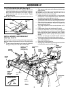
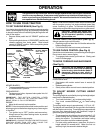
FIG. 4
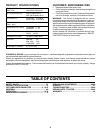
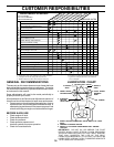
ASSEMBLE GAUGE WHEELS AND
BRACKETS TO MOWER DECK (See Fig. 4)
The gauge wheels are designed to keep the mower deck in
proper position when operating mower. Be sure they are
properly adjusted to ensure optimum mower performance.
• Attach front gauge wheel brackets marked front left
(FL), front right (FR) to mower deck using (3) carriage
bolts and (3) locknuts. For ease of installation do not
tighten locknuts until all carriage bolts have been in-
stalled.
• Attach rear gauge wheel brackets marked rear left (R L),
rear right (RR) to mower deck using (3) carriage bolts and
(3) locknuts. For ease of installation do not tighten
locknuts until all carriage bolts have been installed.
• Slide gauge wheel bar down into bracket channel, Be
sure that gauge wheel bar aligning holes are on top.
Assemble gauge wheels as shown using shoulder bolts,
3/8 washers and 3/8-16 center locknuts and tighten
securely.
• Adjust gauge wheels to highest position for ease of
mower deck assembly.
• Adjust gauge wheels before operating mower as shown
in the operation section of this manual.
SHOULDER
BOLT
GAUGE
WHEEL
3/8-16 CENTER
LOCKNUT
GAUGE
WHEEL
MOUNTING
BRACKET
3/8 WASHER
CARRIAGE
BOLTS
CROWNLOCK
NUT
ADJUSTING
BAR
PIN
RETAINER
SPRING
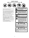
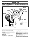
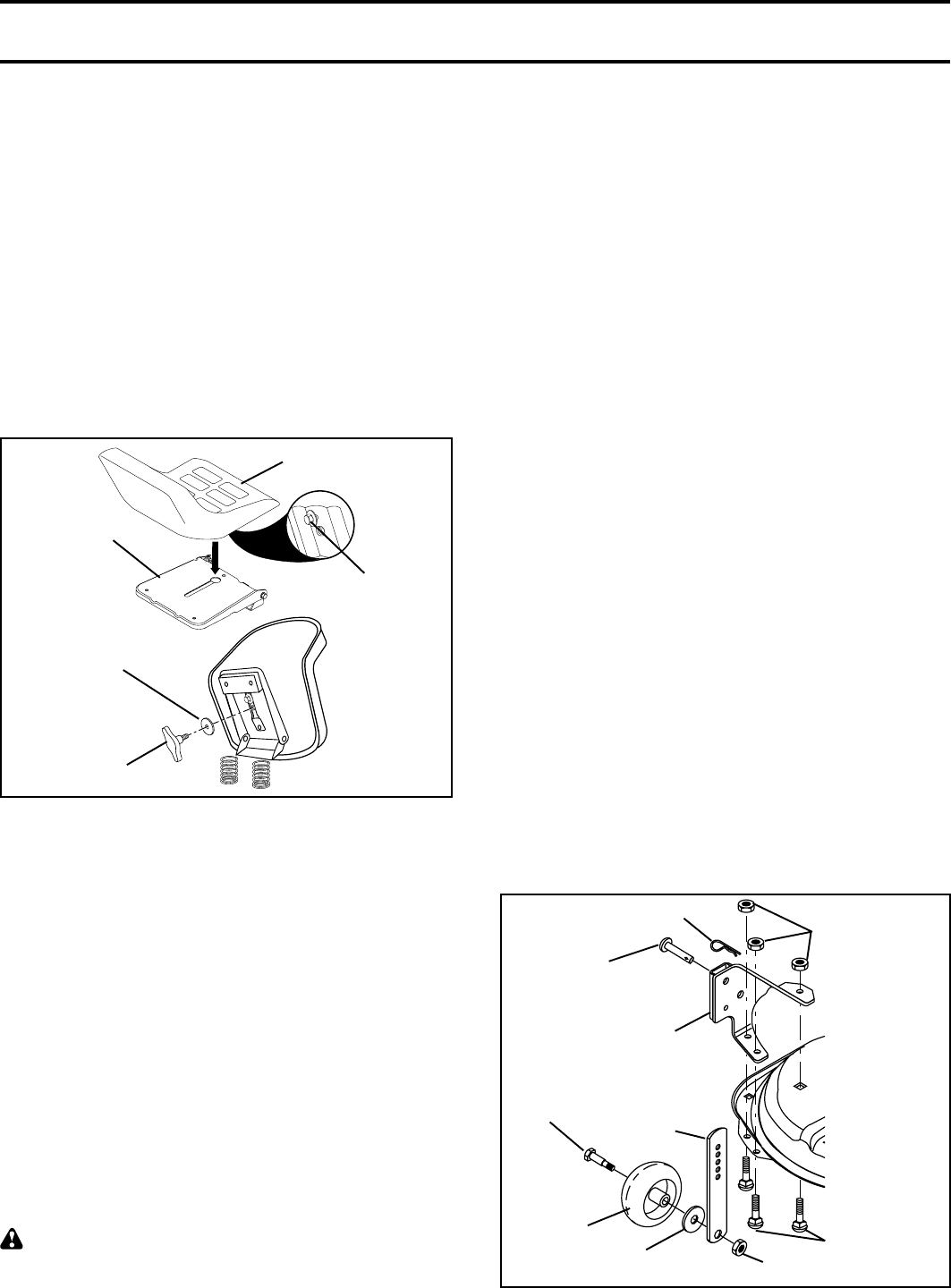
SEAT PAN
SHOULDER
BOLT
ADJUSTMENT
KNOB
FLAT WASHER
SEAT
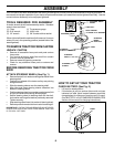
FIG. 3
NOTE: You may now roll or drive your tractor off the skid.
Follow the appropriate instruction below to remove the
tractor from the skid.
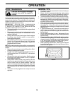
INSTALL SEAT (See Fig. 3)
Adjust seat before tightening adjustment knob.
• Remove adjustment knob and flat washer securing seat
to cardboard packing and set aside for assembly of seat
to tractor.
• Pivot seat upward and remove from the cardboard
packing. Remove the cardboard packing and discard.
• Place seat on seat pan so head of shoulder bolt is
positioned over large slotted hole in pan.
• Push down on seat to engage shoulder bolt in slot and
pull seat towards rear of tractor.
• Pivot seat and pan forward and assemble adjustment
knob and flat washer loosely. Do not tighten.
• Lower seat into operating position and sit on seat.
• Slide seat until a comfortable position is reached which
allows you to press clutch/brake pedal all the way down.
• Get off seat without moving its adjusted position.
• Raise seat and tighten adjustment knob securely.
• Be sure all the above assembly steps have been
completed.
• Check engine oil level and fill fuel tank with gasoline.
• Place freewheel control in “transmission engaged” posi-
tion.
• Sit on seat in operating position, depress brake pedal
and set the parking brake.
• Press lift lever plunger and raise attachment lift lever to
its highest position.
• Start the engine. After engine has started, move throttle
control to idle position.
• Release parking brake.
• Slowly move the motion control lever forward and slowly
drive tractor off skid.
• Apply brake to stop tractor and set parking brake.
• Turn ignition key to “OFF” position.
Continue with the instructions that follow.