


23
SERVICE AND ADJUSTMENTS
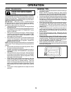
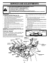
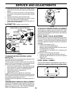
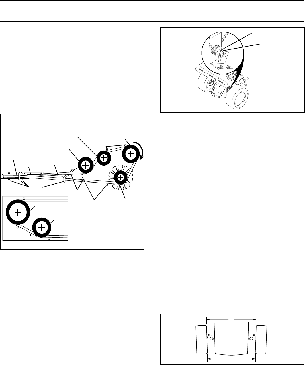
V-IDLER
AS VIEWED FROM BOTTOM
TRACTOR V-BELT DRIVE SCHEMATIC
VIEWED FROM L.H. SIDE OF TRACTOR
ENGINE
PULLEY
BELT
KEEPER
BELT
TWISTS
BELT
KEEPER
ENGINE
PULLEY
CLUTCHING
FLAT IDLER
V-IDLER
ABOVE BELT
KEEPER
BELT
KEEPER
TRANSAXLE
PULLEY
FAN
IDLER
FIG. 27
CLUTCH-
ING IDLER
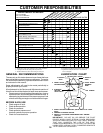
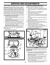
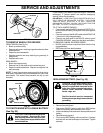
TO ADJUST MOTION CONTROL LEVER
(See Fig. 28)
The motion control lever has been preset at the factory and
adjustment should not be necessary.
If for any reason the motion control lever will not hold its
position while at a selected speed, it may be adjusted at the
friction pack located on the right side of chassis.
• Park tractor on level surface. Stop tractor by turning
ignition key to “OFF” position and engage parking brake.
• Place motion control lever in neutral (N) position.
• While holding locknut, loosen jam nut
• Tighten locknut 1/4 turn.
• While holding locknut, tighten jam nut securely.
NOTE: If for any reason the effort to move the motion control
lever becomes too excessive, reverse the above adjustment
procedure by loosening locknut 1/4 turn.
Road test tractor after adjustment and repeat procedure if
necessary.
TRANSMISSION REMOVAL/REPLACEMENT
Should your transmission require removal for service or
replacement, it should be purged after reinstallation and
before operating the tractor. See “PURGE TRANSMIS-
SION” in the Operation section of this manual.
JAM
NUT
LOCKNUT
FIG. 28
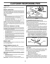
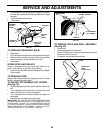
TO ADJUST STEERING WHEEL ALIGNMENT
If steering wheel crossbars are not horizontal (left to right)
when wheels are positioned straight forward, remove steer-
ing wheel and reassemble per instructions in the Assembly
section of this manual.
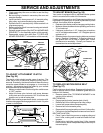
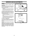
FRONT WHEEL TOE-IN ADJUSTMENT
Front wheel toe-in is required for proper steering operation.
Toe-in was set at the factory and adjustment should not be
necessary. If parts in the front axle or steering mechanism
have been replaced or damaged, check toe-in and adjust if
necessary.
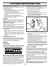
TO CHECK TOE-IN (See Fig. 29)
• Position front wheels straight ahead.
• Measure distance between wheels at front and rear of
tires (dimensions “A” and “B”).
• Front dimension “A” should be 1/8" to 1/4" less than rear
dimension “B”.
TO ADJUST TOE-IN (See Figs. 29 and 30)
• Loosen jam nuts at adjustment sleeves on tie rod.
• Adjust tie rod until dimension “A” is 1/8" to 1/4" less than
dimension “B”.
• Tighten jam nuts securely.
FRONT WHEEL CAMBER
The front wheel camber is not adjustable on your tractor. If
damage has occurred to affect the front wheel camber,
contact your nearest authorized service center/department.
• Route belt on left side, coming from engine pulley,
towards back of tractor and through loop in midspan belt
keeper.
• Place V part of belt into grooves on transaxle and fan
idler pulleys, making sure to route belt inside of all belt
keepers.
• Retighten belt keeper above transaxle pulley.
• Place belt around clutching idlers as shown, making
sure to route belt inside of all belt keepers.
• Check to be sure belt is positioned correctly and is on
proper side of all belt keepers.
• Reinstall mower.
IMPORTANT: CHECK BRAKE ADJUSTMENT.
A
B
FRONT OF TRACTOR
FIG. 29