


14
3. Wash the filter in soap and water.
4. Allow filter to dry .
5. Replace parts.
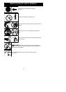
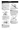
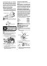
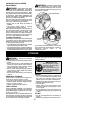
A
ir Filter
Air Filter Cover
Knob
INSPECT MUFFLER AND SPARK
ARRESTING SCREEN
WARNING: Themuffler onthis prod-
uct contains chemicals known to the State of
California to cause cancer.
As your unit is used, carbondeposits buildup
onthe m ufflerand spark a rresting screen and
must be removed toavoid creating a firehaz-
ard o r affecting engine performance.
For normal homeowner use, the muffler and
spark arresting screen will not require any
service. After 50 hours of use, we recom-
mend that your muf fler be serviced or re-
placed by an authorized service dealer.
REPLACE SPARK PLUG
Replace the spark plug each year to ensure
the engine starts easier and runs better . In-
spec t spark plug every 25 hours of usage.
Cleanand/orreplaceasnecessary.Setspark
plug gap at 0.025 inch (0.6 mm). Ignition tim-
ing is fixed and nonadjustable.
NOTE: This spark igni tion system compli es
with the Canadian standard ICES--002.
1. Twist, then pull off spark plug boot.
2. Remove spark plug from cylinder and
discard.
3. Replace with Champion RCJ-6Y spark
plug and tighten securely with a 3/4 inch
(19 mm) socket wrench.
4. Reinstall the spark plug boot.
SERVICE AND ADJUSTMENTS
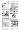
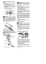
REPLACING THE LINE
For unit to operate properly , the cutting line
should be replaced when line becomes worn to
less than 3 inches (7.5 cm) in le ngth from the
edge of the line exit tunnels on each side of t he
cutting head.
1. Remove and discard worn line before
installing new line.
2. Use only 0.115 inch (3 mm) diameter
Poulan PRO brand cut length line.
3. Insert one end of the line through the
positioning tunnel.
4. Continue to feed line through tunnel until
line is centered (leaving equal amounts
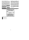
on each side). See illustration below.
Positioning
tunnel
5. Insert ends of line one at a time through
the line exit tunnels.
6. Pullthe line and make sure the line is ex-
tended fully through the tunnels.
Line exit
tunnel
Line exit
tunnel
7. Correctly installed line will be the same
length on both ends.
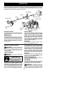
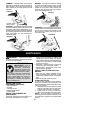
REPLACING T HE CUTTING HEAD
1. Align hole in the dust cup with the hole in
the side of the gearbox by rotating the
dust cup.
2. In se rt a sma l l screwd ri ve r in t o al i g n e d
holes. This will keep the shaft from turning
while removing andinstalling trimmer head.
Screwdriver
3. Whileholding thescrewdriver inposition,
remove trimmer head by turning clock-
wise (looking from bottom of unit).
4. Thread replacement trimmer head onto
the shaft by turning counterclockwise.
Tighten until secure.
5. Remove the screwdriver.