


9
ASSEMB LY
WARNING: If received assembled,
repeat allsteps to ensure yourunit is properly
asse mbled and all fasteners are secure.
Examine parts for dam age. Do not use dam-
aged part s.
NOTE: If you need assi stance or find parts
missing or damaged, call 1-800-554-6723.
It is normal for the fuel filter to rattle in the
empty fuel tank.
Finding fuel or oilresidueon muf fler isnormal
due to carbur etor adjust m ents and testing
done by the manufacturer.
INSTALLING TRIMMER ATTACH-
MENT
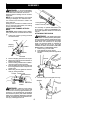
CAUTION: When ins talling trimmer attach-
ment, placethe uniton aflatsurfaceforstabil-
ity.
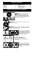
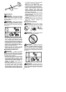
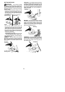
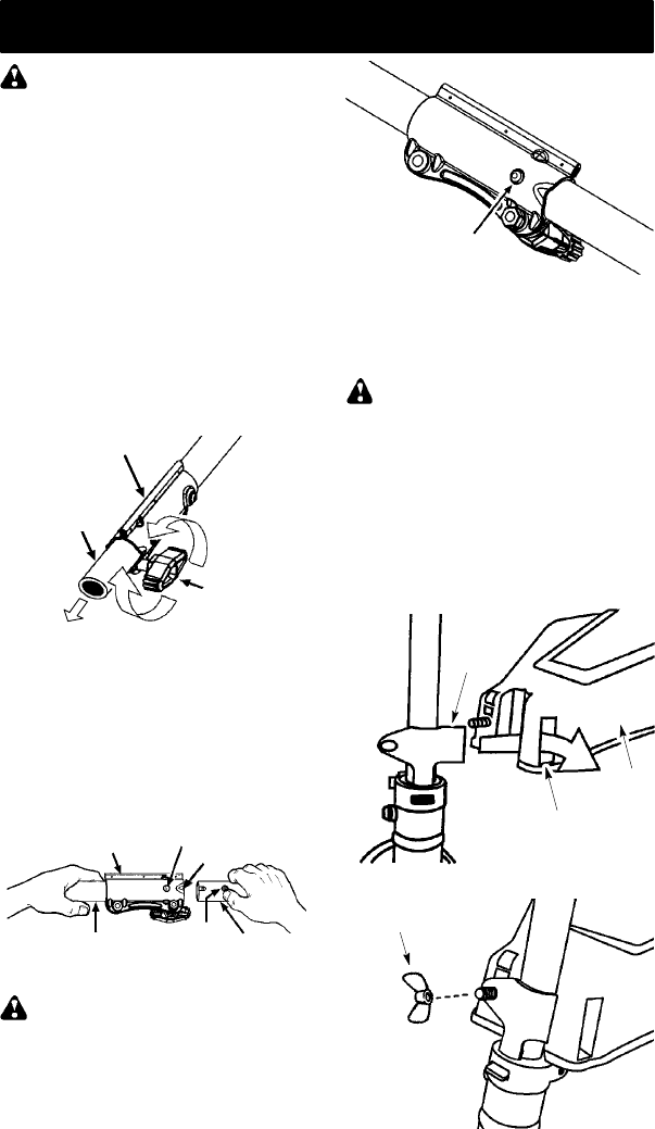
1. Loosen the coupler by turning the knob
counterclockwise.
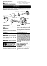
Shipping
protector
Coupler
Knob
LOOSEN
TIGHTE N
2. Remove shipping protector from coupler.
3. Re m ove the sha ft cap f rom the trimme r at-
tach ment (if present).
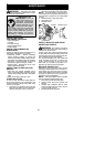
4. Position locking/ release button o fattach-
ment into guide recess of coupler.
5. Push theattachment intothe co upleruntil
the locking/release button snaps into the
primary hole.
6. Before using the unit, tighten the kno b se-
curely by tu rning c lockwi se.
Coupler
Primary Hole
Upper
Shaft
Locking/
Release
Button
Attach m ent
Guide Recess
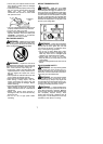
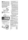
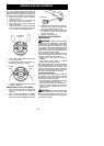
WARNING: Make su re the locking/
release button is locked in the primary hole
and the knob is s ecurely tightened before op-
erating the unit . All attach ments are designed
to be used in the p rimary hole unless otherwise
stat ed in the applicable attachment inst ruction
manual. Using the wrong h ole could l ead toser i-
ous injury or damage to the unit .
Locking/Release
Button in Primary Hole
For assembly of optional attachments (see
list on page 11),refer to the ASSEMBLY sec-
tion of the applicable attachment instruction
manual.
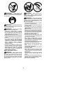
ATTACHING THE SHIELD
WARNING: The shield must be prop-
erly installed. Th e shieldprovi de s partial p rotec-
tion from t he risk o f thrown objects to the opera-
tor and ot hers and i s equippe d with a l ine limiter
blade which cuts excess line to the proper
length. The line limiter blade (on underside of
shield) is sharp and ca n cut you. Fo r proper
orientatio n o f shield, see KNOW YOUR TRIM-
MER illustration i n OPERATION se ction.
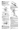
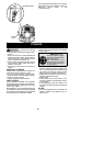
1. Remove wing nut from shield.
2. Insert bracket i nto slot as shown.
3. Pivot shield until bolt p asse s through holein
bracket.
Bracket
Slot
Shield
4. Reinstall wing nut and tighten securely.
WingNut