


Rev. A 1-2-02 P/N 472032
11
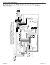
PLUMBING CONNECTIONS
The MiniMax NT Standard heater has the unique
capability of direct schedule 40 PVC plumbing
connections. A set of bulkhead fittings is included with
the MiniMax NT Standard to insure conformity with
Pentair’s recommended PVC plumbing procedure.
Other plumbing connections can be used.
CAUTION
Before operating the heater on a new installation,
turn on the circulation pump and bleed all the air
from the filter using the air relief valve on top of the
filter. Water should flow freely through the heater.
Do not operate the heater unless water in the pool/
spa is at the proper level.
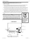
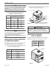
MANUAL BY-PASS
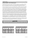
Where the flow rate exceeds the maximum 120
GPM, a manual bypass should be installed and
adjusted. After adjustments are made, the valve
handle should be removed to avoid tampering.
WATER CONNECTIONS
Reversible Inlet/Outlet Connection
The MiniMax NT Standard heater is factory
assembled with right side inlet/outlet water
connections. The inlet/outlet header can be reversed
for left side water connections without removing the
heat exchanger.
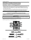
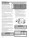
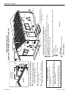
Reversing Water Connections
Tools required:
1/4 in. Screw Driver
9/16 in. Socket and Wrench
1/2 in. & 9/16 in. Open Wrench
1. Remove the right and left large inspection plates.
2. Disconnect all wires from the high-limit
switches except the short jumper wire.
3. Disconnect the pressure switch wiring.
4. Remove the temperature sensing bulb from the
inlet/outlet header. Note: If needed, you may cut
the wire ties holding them together.
5. Remove the 16 bolts holding the main inlet/
outlet head and return head in place, exchange
the heads, using the new tube seals supplied
with the heater, re-install the 16 bolts using
moderate torque.
6. Install the temperature sensing probe by passing
the wires through the hole provided on the left
side of the brace panel. Route wires through the
support bracket.
7. Reconnect all the high limit wires and the
pressure switch wiring, routing the wires
through the same hole as the thermostat sensor
wires.
8. Re-install the two large inspection plates on the
appropriate side.
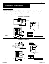
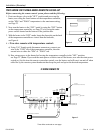
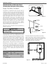
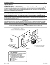
PLUMBING
VALVES
When any equipment is located below the surface of
the pool or spa, valves should be placed in the
circulation piping system to isolate the equipment
from the pool or spa.
Check valves are recommended to prevent back
siphon.
CAUTION
Exercise care when installing chemical feeders so
as to not allow back siphoning of chemical into the
heater, filters or pump.
ledoM)MPG(.niM*)MPG(.xaM
00202021
05203021
00303021
00404021
dednemmocermumixamehtdeecxetonoD*
.gnipipgnitcennocehtrofetarwolf
Installation (Plumbing)
BELOW POOL INSTALLATION
If the heater is below water level, the pressure
switch must be adjusted. This adjustment must be
done by a qualified service technician. See Page 19,
Figure 19.
PUMP
FILTER
POOL
HEATER
CHECK
VALVE
MANUAL
BY-PASS
TO
POOL
GATE
VALVE
CHECK
VALVE
FROM
POOL
Figure 9.