


INSTRUCTIONS
READ AND FOLLOW ALL INSTRUCTIONS
GENERAL:
Our shipping container has been specifically
designed to prevent transit damage. However, any
indications of damage should be carefully noted on
the delivery ticket and a claim filed promptly with the
carrier.
LOCATION:
Locate the pump as close as possible to the pool.
Provide the necessary space around the pump for
future inspection and servicing of the unit. If possible,
allow several inches of clearance below the motor to
floor to allow easy access to mounting screw. Locate
away from pool chemicals to prevent spilling on or
near motor.
INSTALLATION:
The pump suction line should not be smaller than
the pipe size on the inlet of the pump.
Your pump is made of the finest engineering
materials available today. A few simple precautions
taken during the initial installation, will insure many
long years of trouble-free operation.
The threads of pipe fittings screwed into pump
must be sealed with: pipe sealant, Teflon
®
Tape,
R.T.V. or other sealing materials approved for pipe
threads.
Tighten the pump fitting only as much as is
required to insure a tight connection. DO NOT OVER
TIGHTEN.
The piping should be supported independently
and not supported by the pump.
The pump motor must be wired for the proper
voltage, and rotation, in accordance with the wiring
diagram supplied with the motor. All wiring should be
done by a licensed electrician in accordance with
local codes, be certain that the motor frame is
grounded. Use lug on top of motor frame to bond
together motor and all metallic parts of pool, spa or
hot tub structure and to all electrical equipment,
metal conduit, and metal piping within 5 feet of the
inside walls of a swimming pool, spa or hot tub, when
the motor is installed within 5 feet of the inside walls
of the swimming pool, spa or hot tub structure with a
solid copper conductor not less than No. 8 A.W.G.
Motor name plate has voltage, phase, ampere
dr
a
w and other motor inf
or
mation.
Terminal cover
plate or name plate has wiring connection informa-
tion.
The wir
ing to motor should be k
ept as shor
t as
possible and large enough to carry the necessary
current for required length without excessive voltage
drop
.
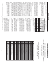
The f
ollo
wing tab
le should be f
ollo
wed to be
sure that the proper wire size is selected. Use as a
guide only.
TABLE OF A.W.G.WIRE SIZE
FOR
SINGLE-PHASE POOL PUMP MOTORS
WARNING - To reduce the risk of injury, do not
permit children to use this product unless they are
closely supervised at all times.
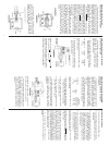
PRIMING:
Fill the pump pot with water before starting the
pump. This may be done by removing clear lid.
Pumps are self priming providing the pump pot is
filled with water. Should you lose this liquid from the
pot accidentally or by draining purposely, it will be
necessary to refill it with liquid before starting. High
Suction Lifts, require additional time for priming.
OPERATION:
After the pump has been filled with water, and the
motor started, allow a few moments for the pump to
start pumping water. If flow does not start within four
minutes, stop motor and refer to (THE TROUBLE
GUIDE).Be sure all suction and discharge valves are
open when the pump is running. Operating the pump
with a closed valve in the system can cause pump
damage.
WINTERIZING:
In areas subject to freezing winter temperatures,
protect pump by removing both drain plugs, one from
the pump volute and one from the pot. Do Not
Replace Plugs, store them in strainer basket for the
winter.
An alternate is to remove the pump and motor
from plumbing and store them indoors in a w
ar
m, dr
y
location.
MAINTENANCE:
The strainer basket in pump should be inspected
and cleaned twice each w
eek.
The str
ainer bask
et is
easy to clean. Loosen the knobs and remove the
clear lid. Remove the basket and clean. Inspect the
Lid
“O”-Ring;
if damaged, replace
.
Install the Clear
Lid, tightening knobs by hand only. The pump seal
requires no lubrication. Refer to motor service center
f
or motors
.
W
ARNING:
NEVER
W
ORK ON PUMP
WHILE IT IS R
UNNING OR POWER IS STILL CONNECTED.
2 7
WIRE LENGTH
50 FEET 100 FEET
VOLTS VOLTS
115 230 115 230
1/3 14 14 14 14
1/2 14 14 12 14
3/4 12 14 12 14
1 12 14 10 14
1 1/2 10 14 10 14
2 10 12 8 12
3 - 12 - 12
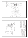
HOW TO ORDER PARTS
WHEN ORDERING PARTS, GIVE
H.P., PUMP SERIAL NO., MODEL NO. & ITEM NO.
TO YOUR LOCAL DEALER
--------------------
H.P., PUMP SERIAL NO. & MODEL NO.
ARE LOCATED ON PUMP
22 1 35-3450 Motor Support (for 5 1/2 Dia.Motor)
21 1 15-4909 Motor Outrigger
20 2 35-4256 Set Screw 1/4” x 20 x 3/8” S.S.
19 4 35-4290 Cap Screw 3/8 - 16 x 1” S.S.
18 8 35-4265 Hex Washer Head Screw 5/16” - 18
17 1 35-4001 3/4 Mechanical Seal
16 1 35-2670 Basket w/Handle - Plastic 700
16 1 35-2656 Basket w/Handle - Plastic 590
15 1 35-2600 Lid O-Ring 700
15 1 35-2602 Lid O-Ring 590
14 1 35-3525 Clear Lid - 700 Plastic
14 1 35-3625 Clear Lid - 590 Plastic
13 2 35-4280 Knob - Pot Plastic
12 1 35-4127 Strainer Pot 700 (Plastic)
12 1 35-4125 Strainer Pot 590 (Plastic)
11 2 154699 Plug-Wing .25” Drain Lgr
10 1 19-2323 O-Ring (Pot to Volute)
9 1 35-3912 Volute - Plastic
8 1 35-2626 O-Ring Volute to Bracket
7 1 35-3220 Impeller RPF 3HP
7 1 35-3050 Impeller RPF 2HP, 21/2HP
7 1 35-3049 Impeller RPF 1 1/2HP, RPA 2HP
7 1 35-3013 Impeller RPF 1HP, 1 1/2HP
7 1 35-3044 Impeller RFP 3/4HP, RPA 1HP
7 1 35-3043 Impeller RFP 1/2HP, RPA 3/4HP
7 1 35-3041 Impeller, RPA 1/2 HP
6 2 15-4445 Hex Nut 3/8 - 16 Cad. Pltd.
5 1 35-4894 Pump Tri Pod Base Plastic
4
1 35-3775 Seal Bracket - Plastic
3 2 35-4294 Screw, Cap 3/8 - 16 x 1 1/4” Cad. Pltd.
2 1 35-3750 Shaft Extension - Bronze
1 Motor
Item Qty. Part No. NAME OR DESCRIPTION
LIST OF MATERIAL OR PARTS LIST
H.P.