


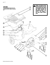
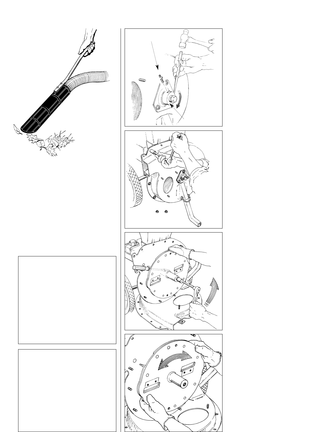
3
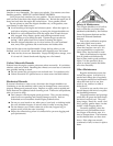
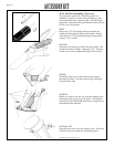
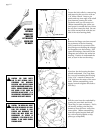
Loosen the lock collar by unscrewing
and removing the set screw with an
1/8” Allen wrench. Insert a pin
punch and tap at an angle with a ball
peen hammer, turning the collar
clockwise until you can remove it.
(Before reassembling the collar, use
sand paper to smooth the burr where
the set screw enters the hub. Be sure
the collar mounts flush with the out-
side of the rotor bearing shaft.)
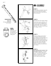
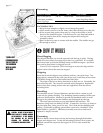
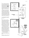
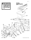
4
Remove the flange nuts from around
the perimeter of the fan housing.
Next, loosen but do not remove the
three flange nuts holding the triangu-
lar flangettes over the bearing. Pull
apart the housings, then take off the
flangettes and remove the entire fan
housing. Position it underneath the
unit, as seen in the next drawing...
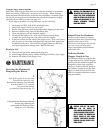
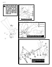
5
Note how the fan housing has been
placed underneath. Put a rag there,
too, to avoid scratching the housing.
Use a 9/16” wrench to remove the
3/8” bolt from the center of the rotor
shaft. (When reassembling, use a
torque wrench to tighten this bolt to
45 ft.-lbs.)
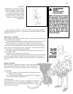
6
Pull the rotor from the crankshaft by
turning the rotor back and forth.
There may be some resistance. Pull it
off steadily, making sure that the
hammers clear the inner wall of the
center plate. (When reassembling,
coat the exposed engine shaft and
key with a liquid graphite or slip
plate type compound.)
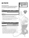
THE VACUUM
(OPTIONAL)
WORKS BEST
WHEN YOU
LET THE NOZZLE
HOVER OVER
THE WASTE.
CAUTION: THE ROTOR WILL COAST
EVEN AFTER THE ENGINE IS OFF. MAKE
SURE THIS ASSEMBLY IS FULLY
STOPPED AND DISCONNECT THE
SPARK PLUG WIRE BEFORE ANY
MAINTENANCE OR SERVICE IS
PERFORMED. IF THE ROTOR IS STILL
TURNING, IT MAY CAUSE SERIOUS
PERSONAL INJURY.
CAUTION: FOR YOUR SAFETY
AND TO MEET NATIONAL SAFETY
STANDARDS, THE DISCHARGE
DEFLECTOR AND HOPPER GUARD
MUST BE MAINTAINED IN GOOD CON-
DITION. SERIOUS PERSONAL INJURY
MAY OCCUR IF THE SHIELD OR
DEFLECTOR ARE NOT INTACT. IT IS
THE OPERATOR’S RESPONSIBILITY TO
MAINTAIN THESE SAFETY DEVICES.
▲
!
▲
!
SET SCREW
LOCK COLLAR
page 14