


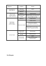

NO.
DESCRIPTION
NO.
DESCRIPTION
1
2
3
4
5
6
7
8
9
10
11
12
13
14
15
16
17
18
19
20
21
22
23
24
25
26
27
28
29
30
31
32
33
34
35
36
37
38
39
40
41
42
Bolt 8×18
Washer 8
Washer 8
Gearbox mounting plate
Bolt 6×90
Bolt 8×25
Release hand seat
Nut 6
Nut 8
Worm reduction gear WPR40 30 1II
Key 4X 20
Screw M6X 20
Clutch inner claw
Clutch outer claw
Spring for drive knob
Circlip 25
Oil cup M6
Outer drive shaft
Inner drive shaft
Spring for drive shaft
Bolt 6×90
Nut 6
Release handle
Main clutch handle
Bolt 8×20
Gearbox support plate
Tension spring
Spring lug
Feed roll bearing204
Feed roll
Nut M10
Wash 10
Bolt 10×35
Nut M14x 1.5
Big wash 14
Screw M6X30
Screw M10×27
Washer 6
Chipper bed blade
Plastic plate
Stickler Assembly
Screw M10×27
43
44
45
46
47
48
49
50
5l
52
53
54
55
56
57
58
59
60
61
62
63
64
65
66
67
68
69
70
71
72
73
74
75
76
77
78
79
80
81
82
83
84
Chipper blade
Flywheel
Key C6*20
Main shaft assembly
Key C10*50
Little around plate
Outer protective cover assembly
Front supporting plate
Rear cover
Bolt 6×12
Bolt M14×1.5×50
Wash l4
Nut M14×1.5
Lower cover
Bolt M10×25
Side plate(I)
Bolt M6×12
Discharge pipe
Support shelf, discharge pipe
Bolt M14×140
Tightening handle
Connecting pin
Protective cover
Bolt M12×1.5×45
Washer 12
Front connecting plate
Washer 22
Nut 22
Protective cover for pulley
Big belt pulley
Small belt pulley
Belt
Small pulley hub
Screw M6×16
BoltM8×50
Feed roll bearing 209
Screw M6×20
Stand base P209
Big pulley hub
Bolt M10×50
Feed roll bearing 207
Stand base P207